Tips & Tricks
What's New in ESI ProCAST 2023
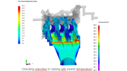
The 'Whats new'-presentation of ProCAST version 2023, with enhancement such as quality of the 3D mesh creation, volume orientation definition and possibility to have multiple scales in results views. This presentationen is intended to bring the most valuable release insights in front of our users and customers and help them to achieve their product design and development goals.
Loïc
Calba
Casting
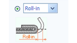
Export of Hemming Contours in ASCII format using Visual-Viewer for SMF
Export in ASCII format for hemming contour doesn't exist in Visual-Viewer, here is shared a simple way to do it
Sureshbabu
Yalavarthi
Sheet Metal Forming
Restart sysweld calculation in batch mode from instants already computed
The time needed to restart a DMP or a SMP computation from instants already computed is very huge due to the way it was processed. Until sysweld version 2020, the selection of part of the model (for restart and DMP) is done with command SAVE … ASCII SELECT. Another command (SELECT TRAN) is known to be faster as the writing is done directly in binary files, but no selection of entity is available with it. Since sysweld version 2021.0, SELECT TRAN has been improved to offer the possibility to use this command to do restart by adding the possibility to select a sub-part of a model during the process. This article consists to show sysweld/systus users how to make a restart calculation in the middle of calculation using "SELECT TRAN" command functionalities
Mandikizinoyou
Taro
Welding & Assembly
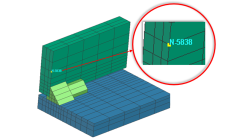
Display mesh nodes in Visual Viewer based on internal number ID
Today it is not possible to display internal number of node within visual viewer. The only way is to display internal number within Sysweld/systus solver, check for the corresponding user defined one and come back in visual viewer to display the user define one. Meanwhile in the .Log file only internal nodes are listed. ITERATION 0 MAX. RESIDUE 0.414E-01 NODE (INT) 14817 COMPONENT 1
Mandikizinoyou
Taro
Multiphysics, Welding & Assembly
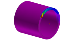
Pipe Welding with Circular Trajectory > 360°
It happens that we need to exceed the welding start position in case of pipe connection. In consequence, we need to have the circular trajectory > 360° so that the heat source could go over one lap.
Yonggang
Duan
Welding & Assembly
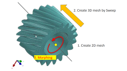
Solid elements morphing by twist in Visual Mesh
In the case of 3D meshes, the term morph can be interpreted as the change of appearance of a graphical object. The morphing process is then defined as the construction of an animated sequence corresponding to the gradual transition between two different objects, so-called source (initial) and target (final) models. The objective of a morphing method is to compute a transformation ensuring a visually pleasant transition between the two, source and target shapes
Mandikizinoyou
Taro
Multiphysics, Welding & Assembly
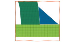
Management Unconnected Mesh in Visual Weld
Meshing is still a difficult task today especially when the geometry of the structure is complex. With the help of “Connect Edges” function in Visual Weld, it is no more mandatory to have mesh nodes connected between components and weld beads. It ensures connection between non-connected mesh properties.The result quality between connected and unconnected computation variants are almost identical and the computation time is nearly the same. The thermal and the mechanical compatibility will be ensured thanks to the automatically generated specific transition elements.
Yonggang
Duan
Welding & Assembly
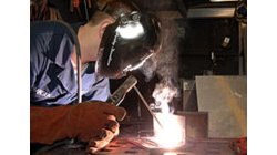
How to simulate welding process with variable weld speed and Heat power ?
In real process, the user changes the velocity depending to the distance already covered or still to cover in welding process. To better reproduce the start and the end of a welding process, the velocity must be able to vary during at least these two phases as well as the heat source power. And to be more generic, this feature introduces a time dependency of the heat source velocity and its power density.
Mandikizinoyou
Taro
Welding & Assembly, Virtual Performance, Virtual Integration Platform
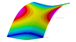
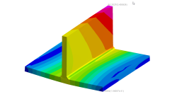
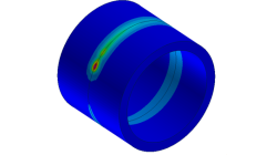
Horse saddle distortion modelling in Visual Weld
Welding of structures involves complex interactions between thermal, metallurgical and mechanical phenomena leading to residual stresses and distortions, which play a major role during subsequent service of these structures. Controlling material characteristics, residual stress and keep distortion within tolerances via the computer can significantly enhance the performance, the quality of the product and the structure’s service life
Mandikizinoyou
Taro
Sheet Metal Forming, Virtual Manufacturing, Multiphysics, Welding & Assembly
Restart Sysweld thermo-metallurgy and mechanical calculation in batch mode
The aim of this article consists to show sysweld/systus users how to perform a restart computation when a calculation run in batch mode is stopped in middle for some reasons or not.
Mandikizinoyou
Taro
Virtual Manufacturing, Multiphysics, Welding & Assembly