Tips & Tricks
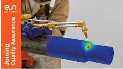
Overview of CSM Welding Advisor in Visual Environment 18.0.2
This tip is to give an overview of new CSM welding advisor in Visual Environment 18.0.2. This new advisor comes in replacement of Visual Welding advisor and uses Assembly solver to perform transient welding simulation.
Mandikizinoyou
Taro
Sheet Metal Forming, Virtual Manufacturing, Welding & Assembly
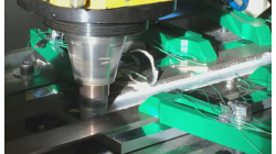
Friction Stir Welding modelling with an Axi-symmetric tool
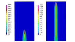
Friction Stir Welding (FSW) is an innovative technology, which allows a solid junction of heterogeneous alloys, using a wear-resistant rotary tool that follows the welding seam. ESI Welding solution allows todays to predict temperature generated by FSW process. The proposed methodology is based on local approach that cannot give global distortion of the welded components. The aim of this article is to show how user can setup it own FSW process and run the computation using Visual Weld application
Mandikizinoyou
Taro
Virtual Manufacturing, Welding & Assembly
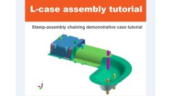
Demonstrator of typical Stamp-Assembly process in automotive BiW manufacturing
New Stamp-Assembly non-confidential tutorial available
Jan
Bejvl
Sheet Metal Forming, Welding & Assembly, Virtual Integration Platform
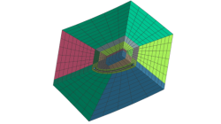
Crack Mesh Application
To insert Crack in a 3D model, an application named Crack Insertion is available
Sandrine
Dischert
Multiphysics, Virtual Integration Platform
Welding simulation with FAST3D method in Visual Weld
A new method is described, which allows to reduce computation time significantly. It is used for transient simulations with moving heat source, mainly for long welds. Its advantage is that it does not require any additional manipulations with the model.
Vsevolod
Troyanov
Welding & Assembly
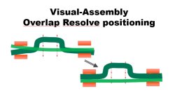
Visual-Assembly Overlap Resolve positioning
The most effective way how to position your distorted components into the clamping system.
Jan
Bejvl
Welding & Assembly, Virtual Integration Platform
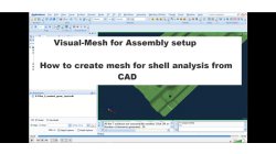
Visual-Mesh for Assembly setup - How to create mesh for shell analysis from CAD.
Short video how to create shell mesh from CAD using Visual-Mesh application.
Ksenia
Troyanova
Welding & Assembly, Virtual Integration Platform

e-café #3 - Customiser l'interface PAM-STAMP
Vous voulez personnaliser votre environnement de travail avec PAMSTAMP ? Cet e-café vous explique comment customiser l'interface en utilisant un workflow dédié et en utilisant des barres d'outils faites sur mesure.
Julien
Charbonneaux
Sheet Metal Forming
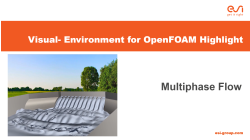
Visual-Environment Highlight of Visual-CFD: Multiphase Flow
In fluid mechanics, multiphase flow is the simultaneous flow of materials with two or more thermodynamic phases. These phases may consist of one chemical component (e.g. flow of water and water vapour), or several different chemical components (e.g. flow of oil and water). Based in user’s intertest and type of problems, multiphase problems can be solved as VOF or euler-euler flow. In Visual-CFD, both approaches are supported for two or more than two phases, with or without heat. The solvers used for multiphase simulations involve the famous MULES method for capturing interfaces between the fluids.
Raj Kumar
Barnawal
Virtual Integration Platform
Visual-Environment Highlight of Visual-CFD: Adjoint Optimisation
The adjoint method has long been considered as the tool of choice for gradient-based optimisation in computational fluid dynamics (CFD). The adjoint method, allows computation of sensitivities, i.e. the derivative of the objective function with respect to the design variables and later shape optimisation. The OpenFOAM supports the continuous adjoint method, it is faster and requires less memory than the discrete adjoint method. However, it requires fine meshes to get desired/optimal output. Visual-CFD makes it even simpler to define and calculate the sensitivities and optimisation with its ease-of-use functionality. Currently it is available for incompressible laminar and turbulent flows with objective functions of lift, drag, momentum for external flow and pressure loss for internal flows.
Raj Kumar
Barnawal
Virtual Integration Platform