Tips & Tricks
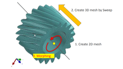
Solid elements morphing by twist in Visual Mesh
In the case of 3D meshes, the term morph can be interpreted as the change of appearance of a graphical object. The morphing process is then defined as the construction of an animated sequence corresponding to the gradual transition between two different objects, so-called source (initial) and target (final) models. The objective of a morphing method is to compute a transformation ensuring a visually pleasant transition between the two, source and target shapes
Mandikizinoyou
Taro
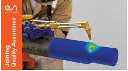
Multiphysics, Welding & Assembly
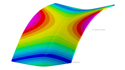
Horse saddle distortion modelling in Visual Weld
Welding of structures involves complex interactions between thermal, metallurgical and mechanical phenomena leading to residual stresses and distortions, which play a major role during subsequent service of these structures. Controlling material characteristics, residual stress and keep distortion within tolerances via the computer can significantly enhance the performance, the quality of the product and the structure’s service life
Mandikizinoyou
Taro
Sheet Metal Forming, Virtual Manufacturing, Multiphysics, Welding & Assembly
Overview of CSM Welding Advisor in Visual Environment 18.0.2
This tip is to give an overview of new CSM welding advisor in Visual Environment 18.0.2. This new advisor comes in replacement of Visual Welding advisor and uses Assembly solver to perform transient welding simulation.
Mandikizinoyou
Taro
Sheet Metal Forming, Virtual Manufacturing, Welding & Assembly
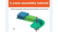
Demonstrator of typical Stamp-Assembly process in automotive BiW manufacturing
New Stamp-Assembly non-confidential tutorial available
Jan
Bejvl
Sheet Metal Forming, Welding & Assembly, Virtual Integration Platform
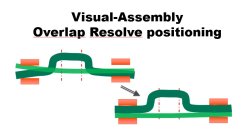
Visual-Assembly Overlap Resolve positioning
The most effective way how to position your distorted components into the clamping system.
Jan
Bejvl
Welding & Assembly, Virtual Integration Platform
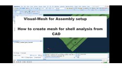
Visual-Mesh for Assembly setup - How to create mesh for shell analysis from CAD.
Short video how to create shell mesh from CAD using Visual-Mesh application.
Ksenia
Troyanova
Welding & Assembly, Virtual Integration Platform
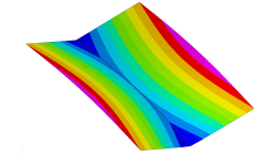
Delta T Offset For Bowing Effect in Assembly Process
In case of butt joint of two plates, in reality, there is an eccentricity e between the neutral phase of bending and the centre of the tendon force caused by the weld which causes the typical horse saddle of a butt welded flat plate.. A functionality Delta T Offset has been developed in order to overcome the limitation due to the shrinkage methodology that cannot provide correct results for a butt joint with a non-symmetrical welding. With this new development, it will be possible to apply an offset value on the thermal loading between upper and lower surfaces of shell. In consequence, the horse saddle effect of a butt welded flat plate is produced with Assembly solution.
Yonggang
Duan
Welding & Assembly
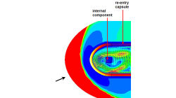
CFD-FASTRAN/CFD-ACE+ coupling for thermal environment simulations
In certain applications, different regions of the computational domain experiences flow conditions that are so different that it is very difficult for a single solver to produce accurate results at the extremes. In many situations, such problems can be separated and solved using loosely coupled solvers. Each solver is chosen to provide highly accurate solutions for the prevailing flow conditions.
Abraham
Meganathan
CFD
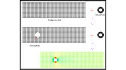
Avoiding Chimera Errors in CFD-FASTRAN
This note discusses a common error encountered by users when trying chimera meshes in CFD-FASTRAN. Such errors are easy to avoid and hopefully this note will assist you.
Abraham
Meganathan
CFD
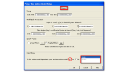
Motion Model Dependencies in CFD-FASTRAN
Moving-body models available in CFD-FASTRAN are highly suited to simulate complex prescribed and six-degree-of-freedom (6DOF) motions of rigid bodies. In many engineering problems, this translates to multiple bodies moving relative to one another.
Abraham
Meganathan
CFD