Tips & Tricks
Visual-CFD Frequently asked questions with solutions
This article collects several tips & tricks for Visual-CFD users
Sunil
Unaune
Virtual Integration Platform
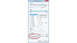
『Simultaneous Display & Trajectory』
Visual-Viewerでは、複数のステートを表示すると同時に指標(node)の軌跡を表示することも可能です。 これにより、指標の動きをより明確にとらえることができます。
Abderrazak
Mejdi
Virtual Integration Platform
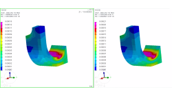
Coupling windows for postreatment visualization
When comparison between results is needed, coupling windows and synchronizing animations is a key tool.
Sandrine
Dischert
Multiphysics, Welding & Assembly, Virtual Integration Platform
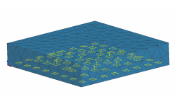
Boundary Layer Mesh tool demonstration
Easily creating a connection between a tetramesh and an hexamesh is possible, using Boundary Layer Mesh tool.
Sandrine
Dischert
Multiphysics, Welding & Assembly, Virtual Integration Platform
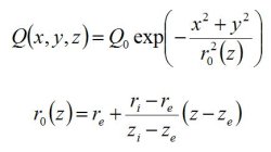
Heat Sources in Sysweld
From finite element point of view, a heat source is modelled in SYSWELD by a volume density of energy named Qr (W/mm3) applied to elements, which move along the welding trajectory.
Yonggang
Duan
Welding & Assembly

How do I create an SEA cavity using shrinkwrap?
How to create FE acoustic cavities with complex shapes
Ricardo
Alvarez
CFD, Vibro-Acoustics
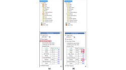
CFD-VIEW Colormap Options: Static, Dynamic, and Cumulative
The Colormap Settings panel in CFD-VIEW assigns colors to data sets. Identical data values on an object are displayed with the same color if they are using the same colormap display. Three options offer the user the opportunity to select the mode for updating the colormap as the underlying data changes, for example during transient simulations. These options are: Static, Dynamic, and Cumulative
Santosh
Kini
CFD
Auto Empty Folders option in CFD-GEOM
When importing large models into CFD-GEOM, you may notice that certain entities listed in the Model Manager may have a red box around them.
Abraham
Meganathan
CFD
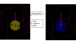
Adding Baffles to an Unstructured domain in CFD-GEOM
While meshing the geometries of industrial significance like mixing tanks, reactor and heat exchangers, we may encounter baffles which have negligible thickness but significant area to impact the physics of the problem in terms of momentum and heat transfer. These surfaces may be free-standing or connected to other surfaces from the domain.
Abraham
Meganathan
CFD

Using Region sources in CFD-VisCART
In order to control grid spacing at user-defined locations, mesh sources are a common tool in CFD-VisCART (Figure 1). Point, Line, Curve, Plane, Box and Surface sources have been available for several years. Cylinder and Sphere sources were introduced a few years back. To extend this tool set further, CFD-VisCART V2013.0 introduced Region sources.
Abraham
Meganathan
CFD