Tips & Tricks
The transient method – the third out of three methods to simulate the heat effects of welding
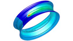
In order to meet different requirements from first design to start of production, three different methods are available in the Virtual Welding & Assembly Suite from ESI. The third one – the transient method – is used when not only distortion but also residual stresses and microstructure need to be evaluated. The part size allows running a heat source gradually. Compare it with a formability evaluation in sheet metal forming. A motorcycle rim may serve as an example.
Harald
Porzner
Welding & Assembly
The instantaneous method – the second out of three methods to simulate the heat effects of welding
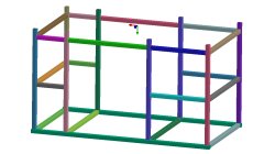
In order to meet different requirements from first design to start of production, three different methods are available in the Virtual Welding & Assembly Suite from ESI. The second one – the instantaneous method – is used when not only distortion but also residual stresses and micro-structure needs to be evaluated, but welded designs are so huge that it would make no more sense to use a classic transient method with a moving heat source – the simulation time would be too long. Compare it with a feasibility evaluation in sheet metal forming. A frame as produced in machine building, with more than 100 welds, may serve as an example.
Harald
Porzner
Welding & Assembly
The shrinkage method – the first out of three methods to simulate the heat effects of welding
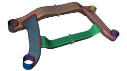
In order to meet different requirements from first design to start of production, three different methods are available in the Virtual Welding & Assembly Suite from ESI. The first one – the shrinkage method – is used in the feasibility and planning phase. Goal is to get as fast as possible an estimation. Compare it with a one-step method in sheet metal forming.
Harald
Porzner
Welding & Assembly
Grouping parts during data import in CFD-VisCART
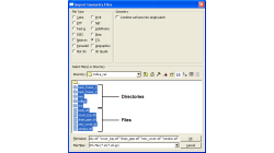
When dealing with complex industrial models such as cars and airplanes, hundreds of parts need to be managed. Each one of these parts may also be subdivided into different components. In order to easily manipulate these different parts and components in CFD-VisCART, you can make use of the grouping feature.
Abraham
Meganathan
CFD

CFD-VisCART: Mesh Extrusion
In most CFD simulations, it is required to place inlets/outlets far enough from the region of interest in order to reduce their influence on the solution. In many applications, this can be done by extruding existing inlets/outlets BC patches away from the domain.
Abraham
Meganathan
CFD

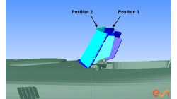
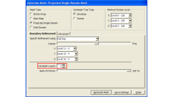
Preserving boundaries between patches with CFD-VisCART’s Single Domain mesher
The ‘Preserve Features’ option does very well in preserving features between geometry patches – as long as the patches are not coplanar (dihedral angle = 0) or include a very small dihedral angle between them.
Abraham
Meganathan
CFD
CFD-VisCART: Suppression of parts for mesh generation
When performing an analysis comparing component A versus component B, it is useful to have both components stored in the same file for physical comparison and documentation purposes. However, when generating the mesh for the analysis, only one of the parts should be considered at a time. The "Suppress" option in CFD-VisCART makes this possible.
Abraham
Meganathan
CFD
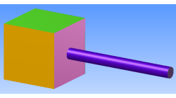
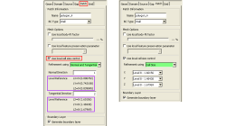
Boundary Layer meshing in CFD-VisCART
In order to accurately capture flow field characteristics, a fine mesh near boundary walls is often needed. This is commonly referred to as the Boundary Layer mesh or simply, Boundary Layers. When dealing with structured meshes, one would cluster grid points near specific boundaries before building mesh faces and blocks. But for an automated mesher, dedicated algorithms are needed to generate boundary layer cells. Both CFD-GEOM and CFD-VisCART are capable of generating boundary layer meshes, and they share the same core algorithm.
Abraham
Meganathan
CFD
"Preserve Feature" option in CFD-VisCART
When dealing with the multi-domain mesher in CFD-VisCART, the ‘Preserve Feature’ option can help you get a mesh that closely follow the original geometry. The meshing algorithm controls the refinement based on the detected ‘Critical Features’ or ‘Outlines’. Therefore, it is very important to detect critical features and outlines prior to mesh generation.
Abraham
Meganathan
CFD
Local cell size control option in CFD-VisCART
It is often necessary to refine or coarsen the mesh in some regions of your model, whether it be to allow the solver to correctly capture gradients of variables (refinement), or reduce the mesh density in some areas to lower the total cell count. In CFD-VisCART, there are many options that enable local mesh refinement.
Abraham
Meganathan
CFD