Tips & Tricks
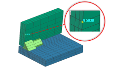
Display mesh nodes in Visual Viewer based on internal number ID
Today it is not possible to display internal number of node within visual viewer. The only way is to display internal number within Sysweld/systus solver, check for the corresponding user defined one and come back in visual viewer to display the user define one. Meanwhile in the .Log file only internal nodes are listed. ITERATION 0 MAX. RESIDUE 0.414E-01 NODE (INT) 14817 COMPONENT 1
Mandikizinoyou
Taro
Multiphysics, Welding & Assembly
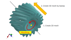
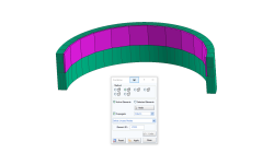
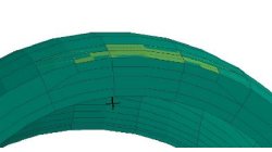
Solid elements morphing by twist in Visual Mesh
In the case of 3D meshes, the term morph can be interpreted as the change of appearance of a graphical object. The morphing process is then defined as the construction of an animated sequence corresponding to the gradual transition between two different objects, so-called source (initial) and target (final) models. The objective of a morphing method is to compute a transformation ensuring a visually pleasant transition between the two, source and target shapes
Mandikizinoyou
Taro
Multiphysics, Welding & Assembly
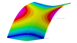
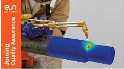
Horse saddle distortion modelling in Visual Weld
Welding of structures involves complex interactions between thermal, metallurgical and mechanical phenomena leading to residual stresses and distortions, which play a major role during subsequent service of these structures. Controlling material characteristics, residual stress and keep distortion within tolerances via the computer can significantly enhance the performance, the quality of the product and the structure’s service life
Mandikizinoyou
Taro
Sheet Metal Forming, Virtual Manufacturing, Multiphysics, Welding & Assembly
Restart Sysweld thermo-metallurgy and mechanical calculation in batch mode
The aim of this article consists to show sysweld/systus users how to perform a restart computation when a calculation run in batch mode is stopped in middle for some reasons or not.
Mandikizinoyou
Taro
Virtual Manufacturing, Multiphysics, Welding & Assembly
Overview of CSM Welding Advisor in Visual Environment 18.0.2
This tip is to give an overview of new CSM welding advisor in Visual Environment 18.0.2. This new advisor comes in replacement of Visual Welding advisor and uses Assembly solver to perform transient welding simulation.
Mandikizinoyou
Taro
Sheet Metal Forming, Virtual Manufacturing, Welding & Assembly
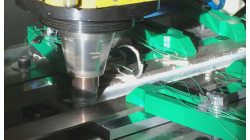
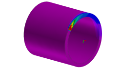
Friction Stir Welding modelling with an Axi-symmetric tool
Friction Stir Welding (FSW) is an innovative technology, which allows a solid junction of heterogeneous alloys, using a wear-resistant rotary tool that follows the welding seam. ESI Welding solution allows todays to predict temperature generated by FSW process. The proposed methodology is based on local approach that cannot give global distortion of the welded components. The aim of this article is to show how user can setup it own FSW process and run the computation using Visual Weld application
Mandikizinoyou
Taro
Virtual Manufacturing, Welding & Assembly
Crack Mesh Application
To insert Crack in a 3D model, an application named Crack Insertion is available
Sandrine
Dischert
Multiphysics, Virtual Integration Platform
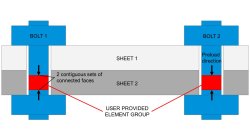
Modelling pretension of Bolts
To simulate bolt pretension, a new medium called PRELOAD has been developed. With this medium, the strain generating the pretension is automatically computed and applied on the model.
Sandrine
Dischert
Multiphysics
3D Combine
As existing 2D Combine in Visual-Mesh, 3D Combine has been introduced to undone refinements.
Sandrine
Dischert
Multiphysics, Virtual Integration Platform
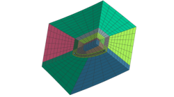
New pattern in Visual-Mesh 3D split
The aim of this new 3D pattern is to allow users to refine mesh on a restricted area
Sandrine
Dischert
Multiphysics, Virtual Integration Platform