Tips & Tricks
Cell Size Growth Control in CFD-VisCART
In CFD-VisCART, the Cartesian cells can split or grow by a minimum factor of 2 because of the intrinsic cartesian-cell-splitting algorithm. Due to this, in some cases, there is a chance that the mesh could grow from dense (at the wall) to coarse (away from the wall) within a short distance.
Abraham
Meganathan
CFD
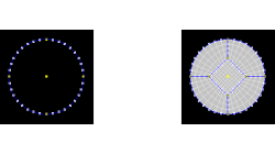
Butterfly Faces Meshing Tool in CFD-GEOM
In CFD-GEOM, a convenient meshing tool called "Butterfly Faces" allows the user to quickly and automatically create a structured mesh for circular topologies. The resulting mesh consists of 5 structured faces (4 sides and 1 core) inside a circle. Parameters are available to set the size of the core and the mesh density.
Abraham
Meganathan
CFD
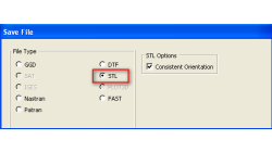
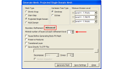
Exporting STL Files From CFD-GEOM
A CFD simulation process starts from an accurate representation of the boundaries that usually originates directly from CAD systems. STL and IGES are two of the most common output formats used as a starting point for mesh generation. STL (StereoLithography) files represent 3D surface geometries using a triangular mesh allowing unambiguous transfer of files from one system to another.
Abraham
Meganathan
CFD
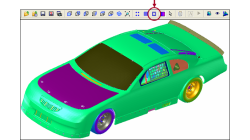
Wireframe Display in CFD-VisCART
Rotation, zoom, pan and other graphical operations require re-drawing of the model in the new position within the graphics window. When dealing with large models, these operations can slow down considerably due to the huge amount of graphical data that needs to be processed and re-drawn.
Abraham
Meganathan
CFD
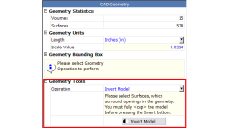
Inverting Models in CFD-CADalyzer
Computational Fluid Dynamics (CFD) requires the discretization of a geometry bounded by it's wetted surfaces. In CAD, the solid parts are created without the corresponding fluid volumes, i.e. negative space.
Abraham
Meganathan
CFD
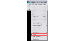
Using Levels in CFD-GEOM
Handling large models in CFD-GEOM is quite easy, but often there are thousands of entities, making it hard to sort out particular entities among them all. For cases like these, a visual grouping mechanism in CFD-GEOM makes viewing such models very efficient. Levels in CFD-GEOM are used as a visual grouping tool, allowing you to Show/Hide certain parts of your model easily and quickly
Abraham
Meganathan
CFD
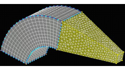
Hybrid Meshing in CFD-GEOM
Hybrid meshes can help in optimizing grids in complex geometries allowing for structured meshes in one part of a geometry, while using unstructured grids in more complex regions. This tip will show you how to create a simple hybrid (structured/tetrahedral) mesh system in CFD-GEOM, as shown in Figure 1.
Abraham
Meganathan
CFD
Creating Multiple Blocks from a Single Mouse Click
Computational Fluid Dynamics initiated in structured grid context for smooth and orthogonal structured grid on relatively simple geometries. Today, CFD has evolved encompass multi block and overlapping structured grid techniques for complex geometries, along with other mesh types such as tetrahedrals, polyhedrals, and prisms.
Abraham
Meganathan
CFD
Visual Display of Bad Cells in CFD-VisCART
Most models have certain parts or regions where the grid density needs to be higher than other areas to accommodate for steep curvatures, sharply changing topology, etc.
Abraham
Meganathan
CFD
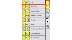
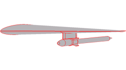
Handling Multiple holes for surface operations in CFD-GEOM
In the past, cutting or filling holes in surfaces with CFD-GEOM required a two step process; 1) pick the surface 2) pick the closed set of curves that forms the hole. Not a bad process but in the case of having to cut the surface with multiple holes, it was quite inefficient since you could only cut one hole at a time.
Abraham
Meganathan
CFD