Tips & Tricks

How do I create an SEA cavity using shrinkwrap?
How to create FE acoustic cavities with complex shapes
Ricardo
Alvarez
CFD, Vibro-Acoustics
Auto Empty Folders option in CFD-GEOM
When importing large models into CFD-GEOM, you may notice that certain entities listed in the Model Manager may have a red box around them.
Abraham
Meganathan
CFD
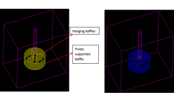
Adding Baffles to an Unstructured domain in CFD-GEOM
While meshing the geometries of industrial significance like mixing tanks, reactor and heat exchangers, we may encounter baffles which have negligible thickness but significant area to impact the physics of the problem in terms of momentum and heat transfer. These surfaces may be free-standing or connected to other surfaces from the domain.
Abraham
Meganathan
CFD

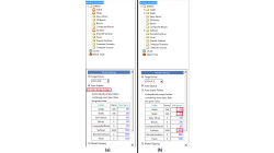
Using Region sources in CFD-VisCART
In order to control grid spacing at user-defined locations, mesh sources are a common tool in CFD-VisCART (Figure 1). Point, Line, Curve, Plane, Box and Surface sources have been available for several years. Cylinder and Sphere sources were introduced a few years back. To extend this tool set further, CFD-VisCART V2013.0 introduced Region sources.
Abraham
Meganathan
CFD
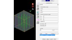
New Mesh Sources in CFD-GEOM for Triangle and Tetrahedral meshing
Corner Point Sources, Surface Interior Sources and Tet Sources have been available in CFD-GEOM for several years, allowing for refinements during certain phases of mesh generation.
Abraham
Meganathan
CFD

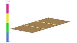
Automatic covering of larger unwanted holes in CFD-VisCART
CFD-VisCART meshing automatically closes or covers holes in the geometry that are smaller in size than the cell size specified at the surfaces. To cover LARGER holes, the ‘Max Hole Size to Cover’ feature can be used. This feature, introduced in V2013.2, works to automatically cover larger holes in the geometry during mesh generation, and thus prevents the mesh from leaking into unwanted regions. This feature is available with all mesh types supported in CFD-VisCART.
Abraham
Meganathan
CFD
Internal injection lines modeling
Internal injection lines on a shell model (i.e. made of internal element edges) are not supported by the parallel solver.
Mathilde
Chabin
Composites

Direct Opening of a mesh
The creation of a RTM project and loading of the model mesh is usually done in 2 steps.
Mathilde
Chabin
Composites
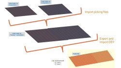
Coupling between PAM-FORM and PAM-RTM: multiple part mapping
Coupling between PAM-FORM 2G and PAM-RTM is done through a .DSY file. Thus, pre-forming process is simulated with PAM-FORM 2G and resulting fiber orientations that will affect permeabilities are transferred to PAM-RTM model setup.
Mathilde
Chabin
Composites
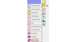
Working with Solids in CFD-GEOM - Part 1: Boolean Operations
Given that today’s users may import several complex parts into CFD-GEOM, this tip will demonstrate how to use the Solid Boolean Union Option to combine several parts into one.
Abraham
Meganathan
CFD