Tips & Tricks

CFD-VisCART: Mesh Extrusion
In most CFD simulations, it is required to place inlets/outlets far enough from the region of interest in order to reduce their influence on the solution. In many applications, this can be done by extruding existing inlets/outlets BC patches away from the domain.
Abraham
Meganathan
CFD

Small collection of 3D meshed symbols for illustration purposes
During a project the need to visualize the functionality in 3D arose and some 3D symbols were created, which are now made available as a goody.
Matthias
Schroeder
Sheet Metal Forming
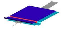
How to find out what forces are working inside the sheet or tube section ?
If you need insight on the restraining force of a geometrical drawbead or want to know the transmitted force in a sheet or tube section, you can define a force gauge.
Matthias
Schroeder
Sheet Metal Forming

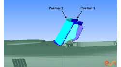
Part to part positioning based on mesh geometry
Sometimes the car coordinate system is not available with the stamped part. So if one wants to map stamp results, to an assembly operation, first of all the part needs to be transformed to the right position.
Matthias
Schroeder
Sheet Metal Forming

How to complete partial part on binder die design with “flat” part boundary?
In the following picture, the die entry radius in the addendum region should disappear smoothly in a flat surface (or infinite radius). In current version, there is no function to directly fulfill this need.
Marie
de Marguerye
Sheet Metal Forming

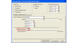
Preserving boundaries between patches with CFD-VisCART’s Single Domain mesher
The ‘Preserve Features’ option does very well in preserving features between geometry patches – as long as the patches are not coplanar (dihedral angle = 0) or include a very small dihedral angle between them.
Abraham
Meganathan
CFD
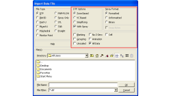
CFD-VisCART: Suppression of parts for mesh generation
When performing an analysis comparing component A versus component B, it is useful to have both components stored in the same file for physical comparison and documentation purposes. However, when generating the mesh for the analysis, only one of the parts should be considered at a time. The "Suppress" option in CFD-VisCART makes this possible.
Abraham
Meganathan
CFD
CFD-VIEW: Working with cell-center data in batch mode
Many improvements have been made in CFD-VIEW that allows the manipulation of cell-center data. The latest cell-center data additions implemented in CFD-VIEW V2011.0 include, for example, support for the MinMax Probe and the Calculator.
Abraham
Meganathan
CFD
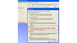
"Per Pixel Lighting" display option in CFD-VIEW
When visualizing CFD solutions, it is often of interest to see a particular range of variable values, and it is therefore useful to be able to clip the surface coloring to that range, as to obtain a clearer view of the areas affected by the variable.
Abraham
Meganathan
CFD
Boundary Layer meshing in CFD-VisCART
In order to accurately capture flow field characteristics, a fine mesh near boundary walls is often needed. This is commonly referred to as the Boundary Layer mesh or simply, Boundary Layers. When dealing with structured meshes, one would cluster grid points near specific boundaries before building mesh faces and blocks. But for an automated mesher, dedicated algorithms are needed to generate boundary layer cells. Both CFD-GEOM and CFD-VisCART are capable of generating boundary layer meshes, and they share the same core algorithm.
Abraham
Meganathan
CFD