Tips & Tricks
Internal injection lines modeling
Internal injection lines on a shell model (i.e. made of internal element edges) are not supported by the parallel solver.
Mathilde
Chabin
Composites

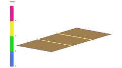
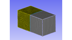
Direct Opening of a mesh
The creation of a RTM project and loading of the model mesh is usually done in 2 steps.
Mathilde
Chabin
Composites
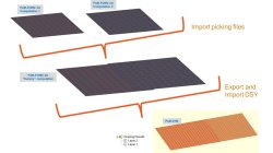
Coupling between PAM-FORM and PAM-RTM: multiple part mapping
Coupling between PAM-FORM 2G and PAM-RTM is done through a .DSY file. Thus, pre-forming process is simulated with PAM-FORM 2G and resulting fiber orientations that will affect permeabilities are transferred to PAM-RTM model setup.
Mathilde
Chabin
Composites
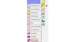
Working with Solids in CFD-GEOM - Part 1: Boolean Operations
Given that today’s users may import several complex parts into CFD-GEOM, this tip will demonstrate how to use the Solid Boolean Union Option to combine several parts into one.
Abraham
Meganathan
CFD
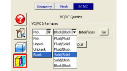
Using the BC/VC Queries tool in CFD-GEOM
Have you ever whished that you could blank/unblank or pick/unpick only interfaces in a CFD-GEOM model? You can now with the BC/VC Queries tool. This tool allows you to pick, unpick, blank or unblank all the interfaces of the current model based on the interface type (Fluid/Fluid, Fluid/Solid, etc.).
Abraham
Meganathan
CFD
How to create Pyramid cells on structured-unstructured domain interfaces in CFD-GEOM
CFD-GEOM can be used to construct a variety of cell shapes: quadrilaterals (2D) and hexahedrals (3D) for structured meshes; triangles (2D) as well as tetrahedrals and polyhedral/honeycomb (3D) for unstructured meshes; prisms and pyramids (3D) for semi-structured meshes.
Abraham
Meganathan
CFD
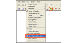
New Exposed Boundaries Visualization tool in CFD-GEOM
One of the various new features introduced in CFD-GEOM V2009.2 is the ‘Exposed Boundaries’ visualization tool. This tool allows users to quickly visualize those areas where closure problems remain in an otherwise closed and “watertight” model.
Abraham
Meganathan
CFD
Repairing Imported CAD Geometries in CFD-GEOM
In most cases, importing CAD files in CFD-GEOM results in a clean geometry that can be directly used for further processing and/or meshing. However, for complex models, it is possible that the imported geometry has missing, untrimmed or defective surfaces that need to be manually repaired.
Abraham
Meganathan
CFD
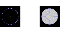
Butterfly Faces Meshing Tool in CFD-GEOM
In CFD-GEOM, a convenient meshing tool called "Butterfly Faces" allows the user to quickly and automatically create a structured mesh for circular topologies. The resulting mesh consists of 5 structured faces (4 sides and 1 core) inside a circle. Parameters are available to set the size of the core and the mesh density.
Abraham
Meganathan
CFD
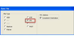
Exporting STL Files From CFD-GEOM
A CFD simulation process starts from an accurate representation of the boundaries that usually originates directly from CAD systems. STL and IGES are two of the most common output formats used as a starting point for mesh generation. STL (StereoLithography) files represent 3D surface geometries using a triangular mesh allowing unambiguous transfer of files from one system to another.
Abraham
Meganathan
CFD