Tips & Tricks
Boundary layer meshing with CFD-ACE+ [video format]
The accuracy of a CFD solution is strongly dependent on how well the mesh resolves geometry and flow features. This is especially true for near wall regions (boundary layer) where viscous forces are not negligible compared to inertial forces.
Abraham
Meganathan
CFD

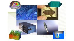
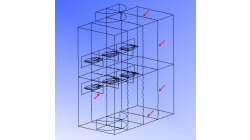
Small collection of 3D meshed symbols for illustration purposes
During a project the need to visualize the functionality in 3D arose and some 3D symbols were created, which are now made available as a goody.
Matthias
Schroeder
Sheet Metal Forming
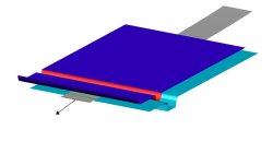
How to find out what forces are working inside the sheet or tube section ?
If you need insight on the restraining force of a geometrical drawbead or want to know the transmitted force in a sheet or tube section, you can define a force gauge.
Matthias
Schroeder
Sheet Metal Forming

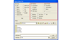
Part to part positioning based on mesh geometry
Sometimes the car coordinate system is not available with the stamped part. So if one wants to map stamp results, to an assembly operation, first of all the part needs to be transformed to the right position.
Matthias
Schroeder
Sheet Metal Forming
CFD-VIEW: Working with cell-center data in batch mode
Many improvements have been made in CFD-VIEW that allows the manipulation of cell-center data. The latest cell-center data additions implemented in CFD-VIEW V2011.0 include, for example, support for the MinMax Probe and the Calculator.
Abraham
Meganathan
CFD
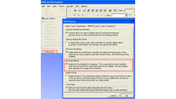
"Per Pixel Lighting" display option in CFD-VIEW
When visualizing CFD solutions, it is often of interest to see a particular range of variable values, and it is therefore useful to be able to clip the surface coloring to that range, as to obtain a clearer view of the areas affected by the variable.
Abraham
Meganathan
CFD
Visualizing decomposed model without zonal interface outlines
Running a simulation in parallel allows quicker turn around for larger and complex problems. Such parallel jobs require the computational domain to be decomposed into multiple zones. Such a multiple-zone file may be inconvenient to post-process in CFD-VIEW because zonal interface outlines will be visible and the original surfaces would have been split. As depicted in figure 1 below, these outlines can be numerous and may therefore hinder the clarity of the model.
Abraham
Meganathan
CFD

Visualizing particle size effect on Spray particle trajectory
When analyzing flow vectors, one can get a general trend of the direction of the flow and locations of recirculation. But what if you need to specifically know where a particle will end up? Maybe release points need to be studied. Then, the size and mass can make a difference in the path a particle travels.
Abraham
Meganathan
CFD
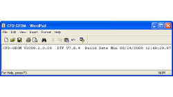
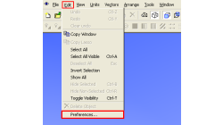
How to check what software version you are running
There is a very fast and easy way to verify what software version you are running for your ESI CFD applications. You most likely know that this information is available for the GUI by clicking on 'Help → About ...', and for solvers by looking in the output file.
Abraham
Meganathan
CFD
Using Macros in CFD-VIEW
In some cases, you might have to perform the same task several times to post-process your results in CFD-VIEW. This can happen for example when you are running a parametric study and need to extract the same information from all the solution files. In this case, it might be time-saving to use the Macro option of CFD-VIEW, especially if obtaining the information necessitates many operations.
Abraham
Meganathan
CFD