Tips & Tricks
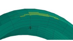
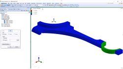
New pattern in Visual-Mesh 3D split
The aim of this new 3D pattern is to allow users to refine mesh on a restricted area
Sandrine
Dischert
Multiphysics, Virtual Integration Platform
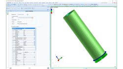
Computation Manager - Basic & Advanced mode
The computation manager help users to generate the computation input with parameters adapted to the model to study
Sandrine
Dischert
Multiphysics
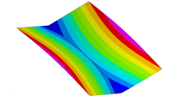
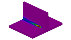
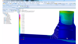
Delta T Offset For Bowing Effect in Assembly Process
In case of butt joint of two plates, in reality, there is an eccentricity e between the neutral phase of bending and the centre of the tendon force caused by the weld which causes the typical horse saddle of a butt welded flat plate.. A functionality Delta T Offset has been developed in order to overcome the limitation due to the shrinkage methodology that cannot provide correct results for a butt joint with a non-symmetrical welding. With this new development, it will be possible to apply an offset value on the thermal loading between upper and lower surfaces of shell. In consequence, the horse saddle effect of a butt welded flat plate is produced with Assembly solution.
Yonggang
Duan
Welding & Assembly
Conversion Files .fdb in .erfh5 on Network Drive
It is not straightforward to do the conversion Files .fdb in .erfh5 on Network Drive in Visual Viewer. In order to make it work properly, it is necessary to map network drive to the local machine. In this way, the files on network could be handled like on local machine and the conversion from fdb to erf will be working properly.
Yonggang
Duan
Multiphysics, Welding & Assembly
Material Properties visualization
Check material properties on model
Sandrine
Dischert
Multiphysics
Cross Section Tool in Visual-SYSTUS
Cross-section creation becomes easy using the brand new Visual-SYSTUS cross-section tool !
Sandrine
Dischert
Multiphysics
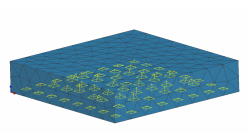
Boundary Layer Mesh tool demonstration
Easily creating a connection between a tetramesh and an hexamesh is possible, using Boundary Layer Mesh tool.
Sandrine
Dischert
Multiphysics, Welding & Assembly, Virtual Integration Platform
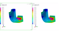
Coupling windows for postreatment visualization
When comparison between results is needed, coupling windows and synchronizing animations is a key tool.
Sandrine
Dischert
Multiphysics, Welding & Assembly, Virtual Integration Platform

Using Region sources in CFD-VisCART
In order to control grid spacing at user-defined locations, mesh sources are a common tool in CFD-VisCART (Figure 1). Point, Line, Curve, Plane, Box and Surface sources have been available for several years. Cylinder and Sphere sources were introduced a few years back. To extend this tool set further, CFD-VisCART V2013.0 introduced Region sources.
Abraham
Meganathan
CFD

Automatic covering of larger unwanted holes in CFD-VisCART
CFD-VisCART meshing automatically closes or covers holes in the geometry that are smaller in size than the cell size specified at the surfaces. To cover LARGER holes, the ‘Max Hole Size to Cover’ feature can be used. This feature, introduced in V2013.2, works to automatically cover larger holes in the geometry during mesh generation, and thus prevents the mesh from leaking into unwanted regions. This feature is available with all mesh types supported in CFD-VisCART.
Abraham
Meganathan
CFD