Tips & Tricks
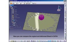
How to import a PAM-STAMP result into CATIA V5 with VRML export format ?
For a comparison of the virtual stamped part and the nominal CATIA V5 part one can use PAM-STAMP, or go back to CATIA. Since the meshed part is not easily converted into surfaces again, one solution is to use an overlay of the CAD part and of a VRML export of the stamp part.
Matthias
Schroeder
Sheet Metal Forming
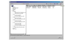
How to encrypt material data sets in PAM-STAMP?
Major automotive companies spend a lot of money to describe all materials used in their simulation processes. To ensure simulation quality also at supplier sites, they want to give the material data sets to them, but not for free. One half of the solution is material encryption, the other a predefined expiration date.
Matthias
Schroeder
Sheet Metal Forming

CFD-VisCART: Mesh Extrusion
In most CFD simulations, it is required to place inlets/outlets far enough from the region of interest in order to reduce their influence on the solution. In many applications, this can be done by extruding existing inlets/outlets BC patches away from the domain.
Abraham
Meganathan
CFD

Small collection of 3D meshed symbols for illustration purposes
During a project the need to visualize the functionality in 3D arose and some 3D symbols were created, which are now made available as a goody.
Matthias
Schroeder
Sheet Metal Forming
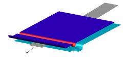
How to find out what forces are working inside the sheet or tube section ?
If you need insight on the restraining force of a geometrical drawbead or want to know the transmitted force in a sheet or tube section, you can define a force gauge.
Matthias
Schroeder
Sheet Metal Forming

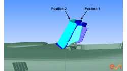
Part to part positioning based on mesh geometry
Sometimes the car coordinate system is not available with the stamped part. So if one wants to map stamp results, to an assembly operation, first of all the part needs to be transformed to the right position.
Matthias
Schroeder
Sheet Metal Forming

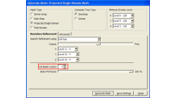
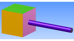
Preserving boundaries between patches with CFD-VisCART’s Single Domain mesher
The ‘Preserve Features’ option does very well in preserving features between geometry patches – as long as the patches are not coplanar (dihedral angle = 0) or include a very small dihedral angle between them.
Abraham
Meganathan
CFD
CFD-VisCART: Suppression of parts for mesh generation
When performing an analysis comparing component A versus component B, it is useful to have both components stored in the same file for physical comparison and documentation purposes. However, when generating the mesh for the analysis, only one of the parts should be considered at a time. The "Suppress" option in CFD-VisCART makes this possible.
Abraham
Meganathan
CFD
Boundary Layer meshing in CFD-VisCART
In order to accurately capture flow field characteristics, a fine mesh near boundary walls is often needed. This is commonly referred to as the Boundary Layer mesh or simply, Boundary Layers. When dealing with structured meshes, one would cluster grid points near specific boundaries before building mesh faces and blocks. But for an automated mesher, dedicated algorithms are needed to generate boundary layer cells. Both CFD-GEOM and CFD-VisCART are capable of generating boundary layer meshes, and they share the same core algorithm.
Abraham
Meganathan
CFD
"Preserve Feature" option in CFD-VisCART
When dealing with the multi-domain mesher in CFD-VisCART, the ‘Preserve Feature’ option can help you get a mesh that closely follow the original geometry. The meshing algorithm controls the refinement based on the detected ‘Critical Features’ or ‘Outlines’. Therefore, it is very important to detect critical features and outlines prior to mesh generation.
Abraham
Meganathan
CFD