Tips & Tricks

Using Region sources in CFD-VisCART
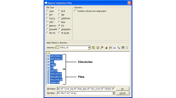
In order to control grid spacing at user-defined locations, mesh sources are a common tool in CFD-VisCART (Figure 1). Point, Line, Curve, Plane, Box and Surface sources have been available for several years. Cylinder and Sphere sources were introduced a few years back. To extend this tool set further, CFD-VisCART V2013.0 introduced Region sources.
Abraham
Meganathan
CFD
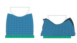
Hints on the usage of linear Tetrahedron (TETR4 / ) elements
This tip provides some background information on the question, when, or when not, to use the linear tetrahedron (TETR4 / ) element in Virtual Performance Solution (VPS)
Jürgen
Rueckert
Virtual Performance
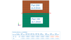
Why do total mass, sum of part masses and sum of nodal masses not match ?
This tip discusses the possible discrepancies in informations concerning total mass, part masses, nodal and element masses, given in the Virtual Performance Solution (VPS) output listing.
Jürgen
Rueckert
Virtual Performance
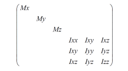
Which moments of inertia to use in added mass (MASS / ) cards ?
This tip discusses the choice of physically meaningful numbers to be used, when moments of inertia need to be specified in an added mass definition.
Jürgen
Rueckert
Virtual Performance
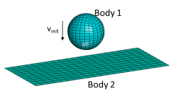
Some possible problems with CNTAC or TIED definitions
This tip discusses some of the reasons that might be responsible for problems with contact or tied definitions in a VPS simulation
Jürgen
Rueckert
Virtual Performance
Relation between Bulk Modulus K, Shear Modulus G, Young's Modulus E and Poisson's ratio ν
This tip explains the relations between the parameters that describe the linear elastic behavior of materials
Jürgen
Rueckert
Virtual Performance
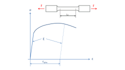
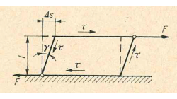
How to convert force-deflection into true stress-strain curves?
This tip helps to convert typical tensile test data into stress-strain curves to be used in many material models of Virtual Performance Solution (VPS)
Jürgen
Rueckert
Virtual Performance

Automatic covering of larger unwanted holes in CFD-VisCART
CFD-VisCART meshing automatically closes or covers holes in the geometry that are smaller in size than the cell size specified at the surfaces. To cover LARGER holes, the ‘Max Hole Size to Cover’ feature can be used. This feature, introduced in V2013.2, works to automatically cover larger holes in the geometry during mesh generation, and thus prevents the mesh from leaking into unwanted regions. This feature is available with all mesh types supported in CFD-VisCART.
Abraham
Meganathan
CFD
Grouping parts during data import in CFD-VisCART
When dealing with complex industrial models such as cars and airplanes, hundreds of parts need to be managed. Each one of these parts may also be subdivided into different components. In order to easily manipulate these different parts and components in CFD-VisCART, you can make use of the grouping feature.
Abraham
Meganathan
CFD

CFD-VisCART: Mesh Extrusion
In most CFD simulations, it is required to place inlets/outlets far enough from the region of interest in order to reduce their influence on the solution. In many applications, this can be done by extruding existing inlets/outlets BC patches away from the domain.
Abraham
Meganathan
CFD