Tips & Tricks
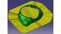
How to create a complex blank holder with PAM-DIEMAKER for CATIA V5
This video shows how the complex blank holder of a double action draw die can be created from multiple segments using a combination of standard CATIA and special PAM-DIEMAKER for CATIA V5 functions all available inside the Blank Holder dialog.
Matthias
Hoss
Sheet Metal Forming
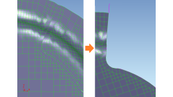
Improve trimming with Overshoot
Trimming in PAM-STAMP can fail due to a too short trimming segment curve leading to not cut properly the blank mesh. This can be solved by using Overshoot option in PAM-DIEMAKER for CATIA V5.
Matthias
Hoss
Sheet Metal Forming
Trim and Shear Angles
Explanations about Trim and Shear Angles
Matthias
Hoss
Sheet Metal Forming

Using Region sources in CFD-VisCART
In order to control grid spacing at user-defined locations, mesh sources are a common tool in CFD-VisCART (Figure 1). Point, Line, Curve, Plane, Box and Surface sources have been available for several years. Cylinder and Sphere sources were introduced a few years back. To extend this tool set further, CFD-VisCART V2013.0 introduced Region sources.
Abraham
Meganathan
CFD
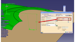
How to define height of constraint UDT profile with respect to the Blankholder?
Method to constrain the height of UDT profile bulge with respect to the Blankholder
Sureshbabu
Yalavarthi
Sheet Metal Forming
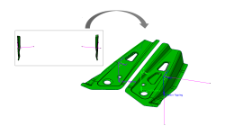
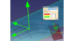
How to define tipping for free double parts with existing forming direction?
Recommendation to position properly the free double parts in case the forming direction is predefined.
Jana
Maradova
Sheet Metal Forming
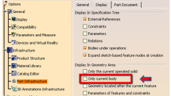
How to get back the hidden Part Definition after accepting dialogue?
Option to deactivate to get back the hidden part definition after accepting dialogue.
Sureshbabu
Yalavarthi
Sheet Metal Forming
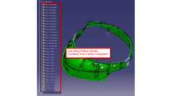
How to improve the update performance on iterations?
Recommendation to optimize the update performance during iterations.
Sureshbabu
Yalavarthi
Sheet Metal Forming

Automatic covering of larger unwanted holes in CFD-VisCART
CFD-VisCART meshing automatically closes or covers holes in the geometry that are smaller in size than the cell size specified at the surfaces. To cover LARGER holes, the ‘Max Hole Size to Cover’ feature can be used. This feature, introduced in V2013.2, works to automatically cover larger holes in the geometry during mesh generation, and thus prevents the mesh from leaking into unwanted regions. This feature is available with all mesh types supported in CFD-VisCART.
Abraham
Meganathan
CFD
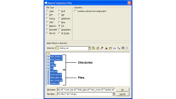
Grouping parts during data import in CFD-VisCART
When dealing with complex industrial models such as cars and airplanes, hundreds of parts need to be managed. Each one of these parts may also be subdivided into different components. In order to easily manipulate these different parts and components in CFD-VisCART, you can make use of the grouping feature.
Abraham
Meganathan
CFD