Tips & Tricks

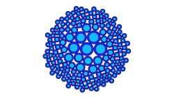
How do I create an SEA cavity using shrinkwrap?
How to create FE acoustic cavities with complex shapes
Ricardo
Alvarez
CFD, Vibro-Acoustics
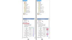
Auto Empty Folders option in CFD-GEOM
When importing large models into CFD-GEOM, you may notice that certain entities listed in the Model Manager may have a red box around them.
Abraham
Meganathan
CFD
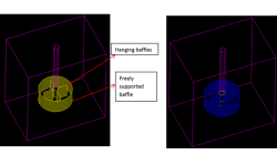
Adding Baffles to an Unstructured domain in CFD-GEOM
While meshing the geometries of industrial significance like mixing tanks, reactor and heat exchangers, we may encounter baffles which have negligible thickness but significant area to impact the physics of the problem in terms of momentum and heat transfer. These surfaces may be free-standing or connected to other surfaces from the domain.
Abraham
Meganathan
CFD
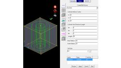
New Mesh Sources in CFD-GEOM for Triangle and Tetrahedral meshing
Corner Point Sources, Surface Interior Sources and Tet Sources have been available in CFD-GEOM for several years, allowing for refinements during certain phases of mesh generation.
Abraham
Meganathan
CFD
How to model Cable Networks & Connectors?
This paper is aimed at describing the modeling process to be applied to the terminal connectors of a Cable Network when focusing on 3D/Multiconductor Transmission Lines (MTL) coupling
Jean-Claude
Kedzia
Electromagnetics
How to avoid oscillatory phenomena with short circuited terminals of Cable Networks ?
Cable Networks with short-circuited terminals may exhibit Common-Mode (CM) currents with a highly oscillatory behavior. This article illustrates one solution to eliminate such behavior by considering lossy dielectric coatings varying with the frequency.
Jean-Claude
Kedzia
Electromagnetics
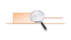
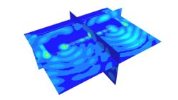
FD Interpolating Scheme near Metallic Structures
This article illustrates the PAM-CEM/FD interpolation scheme applied to compute the tangential electric field along wires’ path running near metallic structures (and aimed at avoiding the management of field components on both sides of the surface).
Jean-Claude
Kedzia
Electromagnetics
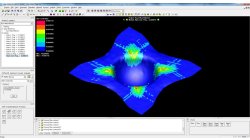
3D/Multiconductor Transmission Lines (MTL) Coupling VS. Stand-Alone FDTD (Accuracy)
This article is aimed at comparing the 3D/Multiconductor Transmission Lines (MTL) coupling accuracy with the PAM-CEM/FD stand-alone use, when applied to simplified wired models. Recommendations for good agreement are also proposed.
Jean-Claude
Kedzia
Electromagnetics
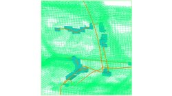
Fiber volume content contour
Two dedicated composites contours are available in PAM-FORM 2G post-processing: Shear angle and fiber directions.
Mathilde
Chabin
Composites
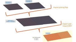
Coupling between PAM-FORM and PAM-RTM: multiple part mapping
Coupling between PAM-FORM 2G and PAM-RTM is done through a .DSY file. Thus, pre-forming process is simulated with PAM-FORM 2G and resulting fiber orientations that will affect permeabilities are transferred to PAM-RTM model setup.
Mathilde
Chabin
Composites