Tips & Tricks
Clipping of X, Y, Z, Arbitrary Cuts and Iso-Surfaces in CFD-VIEW
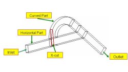
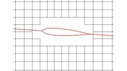
In CFD-VIEW, performing X, Y, Z, arbitrary cut and iso-surface operations on volumes yield surface objects. One may desire to visualize and/or perform calculations in a user specified spatial range of the surface instead of the whole surface.
Abraham
Meganathan
CFD
Blanking Option in CFD-VIEW for Visualizing Chimera Grids
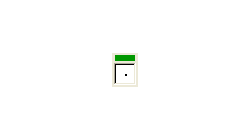
CFD-FASTRAN uses closed surfaces, such as walls or blocked regions, to create Chimera holes (or blanked regions) in a grid. By default, the number of buffer layers is set to 1. This means that a closed surface will cut a hole in any mesh that overlaps it, and the initial "blanking" of grid cells defines the hole.
Abraham
Meganathan
CFD
Using CFD-VIEW Display Types
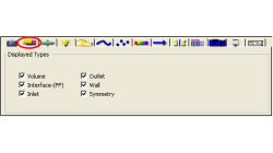
When post processing a simulation in CFD-VIEW, you will often be working with multiple types of objects. Volumes and Surfaces are two types objects that you will most definitely have whether the model is 2D or 3D.
Abraham
Meganathan
CFD
CFD-GEOM Viewer Hot Keys
Most of the time users deal with real world problems which are usually 3D. 3D geometries and grid generation can be difficult to mesh depending on the complexity of the geometry. Working with 3D geometry and grid generation can be made lot faster with effective use of the Hot Keys available in CFD-GEOM.
Abraham
Meganathan
CFD
Surface Projection in CFD-GEOM
The Project Surface tool of CFD-GEOM allows the projection of a single surface onto a collection of surfaces. The collection of surfaces may contain gaps and overlaps, and the resulting projected surface will then covers these imperfections.
Abraham
Meganathan
CFD
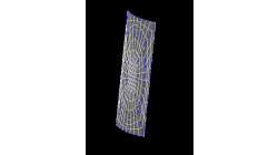
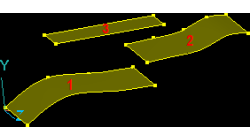
Using Radial Extrusion in CFD-GEOM
The Radial Extrusion tool allows you to extrude structured faces and unstructured surface grids about a specified axis. Extrusion is performed radially about a user-specified axis, typically the center line of the collection of entities being extruded. A variety of options exist for specifying the reference axis and for controlling certain aspects of the extrusion.
Abraham
Meganathan
CFD
Using Interior Sources for Mesh Control in CFD-GEOM
To produce accurate simulation results, it is important to provide adequate mesh resolution in the areas of the model where steep solution gradients are expected. In CFD-GEOM, there are a number of tools available to achieve mesh refinement. One such tool for refining unstructured grids is the interior source option.
Abraham
Meganathan
CFD
CFD-GEOM Filters
Sometimes during the creation of a geometric model it is possible to have overlapping (duplicate) points, line, edges, and faces. This can also occur when CAD files are imported into CFD-GEOM. The user usually finds this situation when trying to do additional operations in CFD-GEOM.
Abraham
Meganathan
CFD
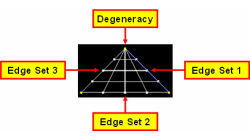
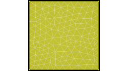
Structured grid in a triangle using CFD-GEOM
CFD-GEOM can create a structured face on a geometry using four edge sets that form a closed circuit. If less than four edge sets are present for the geometry, for example three in a triangle, CFD-GEOM will create a degenerate face at the intersection of the first and third edge sets, as shown Figure 1.
Abraham
Meganathan
CFD
Face Projection on a NURBS Surface in CFD-GEOM
CFD-GEOM provides a face projection tool that enables you to modify grid points such that they adhere to prescribed geometric surfaces. This option is very useful for cases where the underlying surface has curvature in two directions.
Abraham
Meganathan
CFD