Tips & Tricks
Importing an arbitrary STL surface for post-processing in CFD VIEW
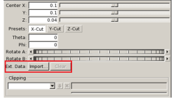
When using the Arbitrary-Cut operator, you have the option to directly import an external surface in STL format into the model. This option, which was first made available in V2013.4, underwent significant performance improvements in V2014.0. This option provides the ability to plot data and process information on any arbitrarily shaped surface. The import process involves reading the STL file and computing the intersections between this surface and the model’s volume cells. Results on the imported surface are interpolated from the intersected volume cells and are independent of the surface mesh size of the STL as long as the surface is properly represented.
Abraham
Meganathan
CFD
Using a template CDL file for quick case set up in CFD-CADalyzer
If your simulations with CFD-CADalyzer typically include the same or similar type of physics, materials and boundary conditions then you can make the case setup process very efficient and quick with the use of a template file - a CDL file that includes the typical simulation settings.
Abraham
Meganathan
CFD

Automatic covering of larger unwanted holes in CFD-VisCART
CFD-VisCART meshing automatically closes or covers holes in the geometry that are smaller in size than the cell size specified at the surfaces. To cover LARGER holes, the ‘Max Hole Size to Cover’ feature can be used. This feature, introduced in V2013.2, works to automatically cover larger holes in the geometry during mesh generation, and thus prevents the mesh from leaking into unwanted regions. This feature is available with all mesh types supported in CFD-VisCART.
Abraham
Meganathan
CFD
Model clipping feature in CFD-VisCART and CFD-GEOM
For better visualization of the geometry and mesh, a model clipping feature was introduced in CFD-VisCART and CFD-GEOM V2013.0. The following sections illustrate the usage and benefits of this feature.
Abraham
Meganathan
CFD
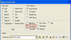
Grouping option for CFD-VIEW Data Import
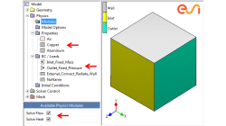
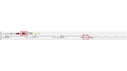
Grouping feature in CFD-ACE+ GUI and CFD-VIEW comes in handy when working with complex industrial models. This feature allows putting BC patches or VC entities into a group that can be manipulated easily, to either set up properties or display specific post-processing attributes.
Abraham
Meganathan
CFD

Improve Productivity Using Scripts [Video Format]
As simulations become more integrated with the design process, engineers often spend time on repeated operations that do not contribute to their productivity. There is a need for tools that could capture, preserve and transfer the knowledge within the organization or to its customers.
Abraham
Meganathan
CFD

CFD-VIEW Scripting is easier than ever with Journaling
In addition to the numerous options and tools available via the CFD-VIEW user interface, the scripting capability of CFD-VIEW allows you to perform complex data processing on your simulation results, and gives you the option to run the post-processing phase of your simulation in batch mode.
Abraham
Meganathan
CFD
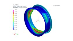
Weld Fatigue analysis based on the Dang Van Criteria
Numerical modeling of fatigue behavior has become critical for welding applications. For this purpose the ‘Dang Van criterion’ has been integrated in SYSWELD for fatigue evaluation of welded structure under multi-axial loadings. The Dang Van fatigue damage criterion is used to predict crack initiation and life duration of components subjected to damaging load. This criterion is based on multi-scale approach which assumes that shakedown occurs before crack initiation.
Harald
Porzner
Welding & Assembly
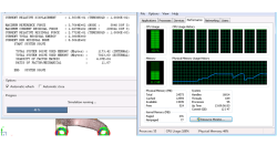
How to report and talk about simulation time in an objective manner
Reporting or talking about simulation time is a difficult subject. In the article a way to manage this problem in an objective manner is given.
Harald
Porzner
Welding & Assembly

Materials in the database - Which material properties to use with respect to the three methods to simulate the heat effects of welding
A material is described with exactly one set of material properties. In simulation engineering - depending on the applied method and the moment in time when the simulation is carried out in the product development cycle - only subsets of a full material data set might be required. In this article is outlined which subset is used for which purpose, what is available in the database, and what can be simulated.
Harald
Porzner
Welding & Assembly