Tips & Tricks
How to Obtain Best Results within Reasonable Time from a Heat Treatment Simulation
Heat treated parts are in most cases not clamped during heat treatment, for an FEM analysis, at least a static determined clamping is needed that does not allow any rigid body motion.
Yonggang
Duan
Welding & Assembly
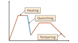
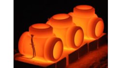
Stamping/HT Chaining of 3D Ring - Restart tool in Visual Heat Treatment
This article is to show effects of heat treatment on stresses when industrial mechanical parts are stamped (or welded) by 3 typical heat treatment steps: Heating, Quenching and Tempering. Tempering is generally considered effective in relieving stresses induced by quenching in addition to lowering hardness to within a specified range, or meeting certain mechanical property requirements.
Yonggang
Duan
Welding & Assembly
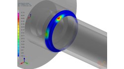
Heat Power display in Visual Weld
The aim of this development in Visual Weld 14.5 + Sysweld 2019.0 is to display the Power Density. Currently, this functionality is only available in the old SysWeld GUI. The new functionality "Heat Power Display" is available through the "Welding Utilities" menu of Visual Weld.
Yonggang
Duan
Welding & Assembly
Conversion Files .fdb in .erfh5 on Network Drive
It is not straightforward to do the conversion Files .fdb in .erfh5 on Network Drive in Visual Viewer. In order to make it work properly, it is necessary to map network drive to the local machine. In this way, the files on network could be handled like on local machine and the conversion from fdb to erf will be working properly.
Yonggang
Duan
Multiphysics, Welding & Assembly
Crash when launching Visual on CentOS
On Linux, at moment of launching Visual-Environmnet, crash happens after having selected Visual Weld. It is possible to try following steps to solve the problem. - Launching Visual in debug mode - Downgrade GlibC to 2.12 - Install freshly NTP
Yonggang
Duan
Virtual Integration Platform, Welding & Assembly
Boundary Layer Mesh tool demonstration
Easily creating a connection between a tetramesh and an hexamesh is possible, using Boundary Layer Mesh tool.
Sandrine
Dischert
Multiphysics, Welding & Assembly, Virtual Integration Platform

Using Region sources in CFD-VisCART
In order to control grid spacing at user-defined locations, mesh sources are a common tool in CFD-VisCART (Figure 1). Point, Line, Curve, Plane, Box and Surface sources have been available for several years. Cylinder and Sphere sources were introduced a few years back. To extend this tool set further, CFD-VisCART V2013.0 introduced Region sources.
Abraham
Meganathan
CFD

Automatic covering of larger unwanted holes in CFD-VisCART
CFD-VisCART meshing automatically closes or covers holes in the geometry that are smaller in size than the cell size specified at the surfaces. To cover LARGER holes, the ‘Max Hole Size to Cover’ feature can be used. This feature, introduced in V2013.2, works to automatically cover larger holes in the geometry during mesh generation, and thus prevents the mesh from leaking into unwanted regions. This feature is available with all mesh types supported in CFD-VisCART.
Abraham
Meganathan
CFD
Grouping parts during data import in CFD-VisCART
When dealing with complex industrial models such as cars and airplanes, hundreds of parts need to be managed. Each one of these parts may also be subdivided into different components. In order to easily manipulate these different parts and components in CFD-VisCART, you can make use of the grouping feature.
Abraham
Meganathan
CFD

CFD-VisCART: Mesh Extrusion
In most CFD simulations, it is required to place inlets/outlets far enough from the region of interest in order to reduce their influence on the solution. In many applications, this can be done by extruding existing inlets/outlets BC patches away from the domain.
Abraham
Meganathan
CFD