Tips & Tricks
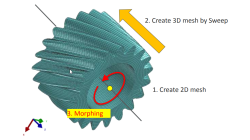
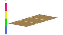
Solid elements morphing by twist in Visual Mesh
In the case of 3D meshes, the term morph can be interpreted as the change of appearance of a graphical object. The morphing process is then defined as the construction of an animated sequence corresponding to the gradual transition between two different objects, so-called source (initial) and target (final) models. The objective of a morphing method is to compute a transformation ensuring a visually pleasant transition between the two, source and target shapes
Mandikizinoyou
Taro
Multiphysics, Welding & Assembly

Demonstrator of typical Stamp-Assembly process in automotive BiW manufacturing
New Stamp-Assembly non-confidential tutorial available
Jan
Bejvl
Sheet Metal Forming, Welding & Assembly, Virtual Integration Platform
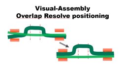
Visual-Assembly Overlap Resolve positioning
The most effective way how to position your distorted components into the clamping system.
Jan
Bejvl
Welding & Assembly, Virtual Integration Platform
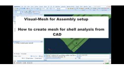
Visual-Mesh for Assembly setup - How to create mesh for shell analysis from CAD.
Short video how to create shell mesh from CAD using Visual-Mesh application.
Ksenia
Troyanova
Welding & Assembly, Virtual Integration Platform
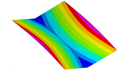
Delta T Offset For Bowing Effect in Assembly Process
In case of butt joint of two plates, in reality, there is an eccentricity e between the neutral phase of bending and the centre of the tendon force caused by the weld which causes the typical horse saddle of a butt welded flat plate.. A functionality Delta T Offset has been developed in order to overcome the limitation due to the shrinkage methodology that cannot provide correct results for a butt joint with a non-symmetrical welding. With this new development, it will be possible to apply an offset value on the thermal loading between upper and lower surfaces of shell. In consequence, the horse saddle effect of a butt welded flat plate is produced with Assembly solution.
Yonggang
Duan
Welding & Assembly
Internal injection lines modeling
Internal injection lines on a shell model (i.e. made of internal element edges) are not supported by the parallel solver.
Mathilde
Chabin
Composites

Direct Opening of a mesh
The creation of a RTM project and loading of the model mesh is usually done in 2 steps.
Mathilde
Chabin
Composites
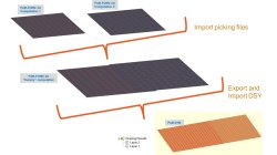
Coupling between PAM-FORM and PAM-RTM: multiple part mapping
Coupling between PAM-FORM 2G and PAM-RTM is done through a .DSY file. Thus, pre-forming process is simulated with PAM-FORM 2G and resulting fiber orientations that will affect permeabilities are transferred to PAM-RTM model setup.
Mathilde
Chabin
Composites
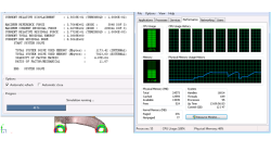
How to report and talk about simulation time in an objective manner
Reporting or talking about simulation time is a difficult subject. In the article a way to manage this problem in an objective manner is given.
Harald
Porzner
Welding & Assembly

Materials in the database - Which material properties to use with respect to the three methods to simulate the heat effects of welding
A material is described with exactly one set of material properties. In simulation engineering - depending on the applied method and the moment in time when the simulation is carried out in the product development cycle - only subsets of a full material data set might be required. In this article is outlined which subset is used for which purpose, what is available in the database, and what can be simulated.
Harald
Porzner
Welding & Assembly