Tips & Tricks
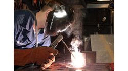
How to simulate welding process with variable weld speed and Heat power ?
In real process, the user changes the velocity depending to the distance already covered or still to cover in welding process. To better reproduce the start and the end of a welding process, the velocity must be able to vary during at least these two phases as well as the heat source power. And to be more generic, this feature introduces a time dependency of the heat source velocity and its power density.
Mandikizinoyou
Taro
Welding & Assembly, Virtual Performance, Virtual Integration Platform
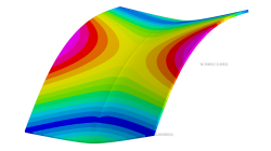
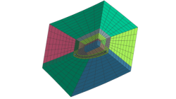
Horse saddle distortion modelling in Visual Weld
Welding of structures involves complex interactions between thermal, metallurgical and mechanical phenomena leading to residual stresses and distortions, which play a major role during subsequent service of these structures. Controlling material characteristics, residual stress and keep distortion within tolerances via the computer can significantly enhance the performance, the quality of the product and the structure’s service life
Mandikizinoyou
Taro
Sheet Metal Forming, Virtual Manufacturing, Multiphysics, Welding & Assembly
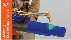
Overview of CSM Welding Advisor in Visual Environment 18.0.2
This tip is to give an overview of new CSM welding advisor in Visual Environment 18.0.2. This new advisor comes in replacement of Visual Welding advisor and uses Assembly solver to perform transient welding simulation.
Mandikizinoyou
Taro
Sheet Metal Forming, Virtual Manufacturing, Welding & Assembly
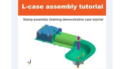
Demonstrator of typical Stamp-Assembly process in automotive BiW manufacturing
New Stamp-Assembly non-confidential tutorial available
Jan
Bejvl
Sheet Metal Forming, Welding & Assembly, Virtual Integration Platform
Crack Mesh Application
To insert Crack in a 3D model, an application named Crack Insertion is available
Sandrine
Dischert
Multiphysics, Virtual Integration Platform
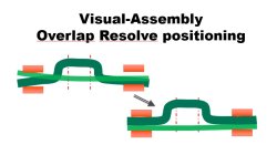
Visual-Assembly Overlap Resolve positioning
The most effective way how to position your distorted components into the clamping system.
Jan
Bejvl
Welding & Assembly, Virtual Integration Platform
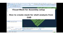
Visual-Mesh for Assembly setup - How to create mesh for shell analysis from CAD.
Short video how to create shell mesh from CAD using Visual-Mesh application.
Ksenia
Troyanova
Welding & Assembly, Virtual Integration Platform

Visual-Environment Highlight of Visual-CFD: Multiphase Flow
In fluid mechanics, multiphase flow is the simultaneous flow of materials with two or more thermodynamic phases. These phases may consist of one chemical component (e.g. flow of water and water vapour), or several different chemical components (e.g. flow of oil and water). Based in user’s intertest and type of problems, multiphase problems can be solved as VOF or euler-euler flow. In Visual-CFD, both approaches are supported for two or more than two phases, with or without heat. The solvers used for multiphase simulations involve the famous MULES method for capturing interfaces between the fluids.
Raj Kumar
Barnawal
Virtual Integration Platform

Visual-Environment Highlight of Visual-CFD: Adjoint Optimisation
The adjoint method has long been considered as the tool of choice for gradient-based optimisation in computational fluid dynamics (CFD). The adjoint method, allows computation of sensitivities, i.e. the derivative of the objective function with respect to the design variables and later shape optimisation. The OpenFOAM supports the continuous adjoint method, it is faster and requires less memory than the discrete adjoint method. However, it requires fine meshes to get desired/optimal output. Visual-CFD makes it even simpler to define and calculate the sensitivities and optimisation with its ease-of-use functionality. Currently it is available for incompressible laminar and turbulent flows with objective functions of lift, drag, momentum for external flow and pressure loss for internal flows.
Raj Kumar
Barnawal
Virtual Integration Platform

Visual-Environment Highlight of Visual-CFD: Reacting Species
Modelling reactive systems is numerically expensive since the non-linear reaction kinetics leads to stiff-ODE systems in the species and energy conservation equations. Special solution algorithms, capable of handling these stiff systems of equations, different ODE solvers are supported for the same. Strategies to reduce the numerical effort to solve reactive flows include chemistry tabulation, which is also supported. A critical choice in simulating reactive flows is the combustion model, there are different combustion model has been supported which can be picked based on user’s choice. Enough intelligence has been put in Visual-CFD for user, while creating chemical reaction, in case reaction is not stoichiometrically balanced user will be warned for the same.
Raj Kumar
Barnawal
Virtual Integration Platform