Tips & Tricks

Using Region sources in CFD-VisCART
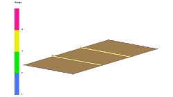
In order to control grid spacing at user-defined locations, mesh sources are a common tool in CFD-VisCART (Figure 1). Point, Line, Curve, Plane, Box and Surface sources have been available for several years. Cylinder and Sphere sources were introduced a few years back. To extend this tool set further, CFD-VisCART V2013.0 introduced Region sources.
Abraham
Meganathan
CFD

Automatic covering of larger unwanted holes in CFD-VisCART
CFD-VisCART meshing automatically closes or covers holes in the geometry that are smaller in size than the cell size specified at the surfaces. To cover LARGER holes, the ‘Max Hole Size to Cover’ feature can be used. This feature, introduced in V2013.2, works to automatically cover larger holes in the geometry during mesh generation, and thus prevents the mesh from leaking into unwanted regions. This feature is available with all mesh types supported in CFD-VisCART.
Abraham
Meganathan
CFD
Internal injection lines modeling
Internal injection lines on a shell model (i.e. made of internal element edges) are not supported by the parallel solver.
Mathilde
Chabin
Composites

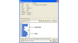
Direct Opening of a mesh
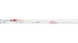
The creation of a RTM project and loading of the model mesh is usually done in 2 steps.
Mathilde
Chabin
Composites
Coupling between PAM-FORM and PAM-RTM: multiple part mapping
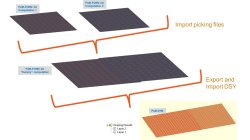
Coupling between PAM-FORM 2G and PAM-RTM is done through a .DSY file. Thus, pre-forming process is simulated with PAM-FORM 2G and resulting fiber orientations that will affect permeabilities are transferred to PAM-RTM model setup.
Mathilde
Chabin
Composites
Model clipping feature in CFD-VisCART and CFD-GEOM
For better visualization of the geometry and mesh, a model clipping feature was introduced in CFD-VisCART and CFD-GEOM V2013.0. The following sections illustrate the usage and benefits of this feature.
Abraham
Meganathan
CFD
Improve Productivity Using Scripts [Video Format]
As simulations become more integrated with the design process, engineers often spend time on repeated operations that do not contribute to their productivity. There is a need for tools that could capture, preserve and transfer the knowledge within the organization or to its customers.
Abraham
Meganathan
CFD
Grouping parts during data import in CFD-VisCART
When dealing with complex industrial models such as cars and airplanes, hundreds of parts need to be managed. Each one of these parts may also be subdivided into different components. In order to easily manipulate these different parts and components in CFD-VisCART, you can make use of the grouping feature.
Abraham
Meganathan
CFD

Boundary layer meshing with CFD-ACE+ [video format]
The accuracy of a CFD solution is strongly dependent on how well the mesh resolves geometry and flow features. This is especially true for near wall regions (boundary layer) where viscous forces are not negligible compared to inertial forces.
Abraham
Meganathan
CFD

CFD-VisCART: Mesh Extrusion
In most CFD simulations, it is required to place inlets/outlets far enough from the region of interest in order to reduce their influence on the solution. In many applications, this can be done by extruding existing inlets/outlets BC patches away from the domain.
Abraham
Meganathan
CFD