Tips & Tricks
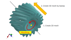
Solid elements morphing by twist in Visual Mesh
In the case of 3D meshes, the term morph can be interpreted as the change of appearance of a graphical object. The morphing process is then defined as the construction of an animated sequence corresponding to the gradual transition between two different objects, so-called source (initial) and target (final) models. The objective of a morphing method is to compute a transformation ensuring a visually pleasant transition between the two, source and target shapes
Mandikizinoyou
Taro
Multiphysics, Welding & Assembly

Demonstrator of typical Stamp-Assembly process in automotive BiW manufacturing
New Stamp-Assembly non-confidential tutorial available
Jan
Bejvl
Sheet Metal Forming, Welding & Assembly, Virtual Integration Platform
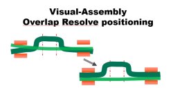
Visual-Assembly Overlap Resolve positioning
The most effective way how to position your distorted components into the clamping system.
Jan
Bejvl
Welding & Assembly, Virtual Integration Platform
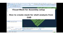
Visual-Mesh for Assembly setup - How to create mesh for shell analysis from CAD.
Short video how to create shell mesh from CAD using Visual-Mesh application.
Ksenia
Troyanova
Welding & Assembly, Virtual Integration Platform
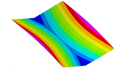
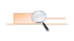
Delta T Offset For Bowing Effect in Assembly Process
In case of butt joint of two plates, in reality, there is an eccentricity e between the neutral phase of bending and the centre of the tendon force caused by the weld which causes the typical horse saddle of a butt welded flat plate.. A functionality Delta T Offset has been developed in order to overcome the limitation due to the shrinkage methodology that cannot provide correct results for a butt joint with a non-symmetrical welding. With this new development, it will be possible to apply an offset value on the thermal loading between upper and lower surfaces of shell. In consequence, the horse saddle effect of a butt welded flat plate is produced with Assembly solution.
Yonggang
Duan
Welding & Assembly
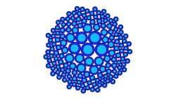
How to model Cable Networks & Connectors?
This paper is aimed at describing the modeling process to be applied to the terminal connectors of a Cable Network when focusing on 3D/Multiconductor Transmission Lines (MTL) coupling
Jean-Claude
Kedzia
Electromagnetics
How to avoid oscillatory phenomena with short circuited terminals of Cable Networks ?
Cable Networks with short-circuited terminals may exhibit Common-Mode (CM) currents with a highly oscillatory behavior. This article illustrates one solution to eliminate such behavior by considering lossy dielectric coatings varying with the frequency.
Jean-Claude
Kedzia
Electromagnetics
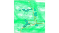
FD Interpolating Scheme near Metallic Structures
This article illustrates the PAM-CEM/FD interpolation scheme applied to compute the tangential electric field along wires’ path running near metallic structures (and aimed at avoiding the management of field components on both sides of the surface).
Jean-Claude
Kedzia
Electromagnetics
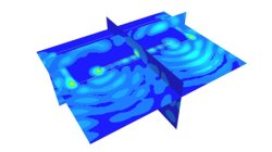
3D/Multiconductor Transmission Lines (MTL) Coupling VS. Stand-Alone FDTD (Accuracy)
This article is aimed at comparing the 3D/Multiconductor Transmission Lines (MTL) coupling accuracy with the PAM-CEM/FD stand-alone use, when applied to simplified wired models. Recommendations for good agreement are also proposed.
Jean-Claude
Kedzia
Electromagnetics