Tips & Tricks
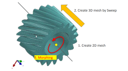
Solid elements morphing by twist in Visual Mesh
In the case of 3D meshes, the term morph can be interpreted as the change of appearance of a graphical object. The morphing process is then defined as the construction of an animated sequence corresponding to the gradual transition between two different objects, so-called source (initial) and target (final) models. The objective of a morphing method is to compute a transformation ensuring a visually pleasant transition between the two, source and target shapes
Mandikizinoyou
Taro
Multiphysics, Welding & Assembly
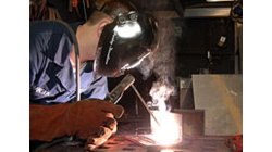
How to simulate welding process with variable weld speed and Heat power ?
In real process, the user changes the velocity depending to the distance already covered or still to cover in welding process. To better reproduce the start and the end of a welding process, the velocity must be able to vary during at least these two phases as well as the heat source power. And to be more generic, this feature introduces a time dependency of the heat source velocity and its power density.
Mandikizinoyou
Taro
Welding & Assembly, Virtual Performance, Virtual Integration Platform
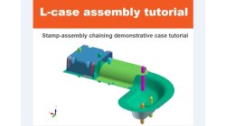
Demonstrator of typical Stamp-Assembly process in automotive BiW manufacturing
New Stamp-Assembly non-confidential tutorial available
Jan
Bejvl
Sheet Metal Forming, Welding & Assembly, Virtual Integration Platform
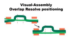
Visual-Assembly Overlap Resolve positioning
The most effective way how to position your distorted components into the clamping system.
Jan
Bejvl
Welding & Assembly, Virtual Integration Platform
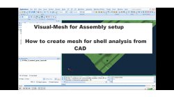
Visual-Mesh for Assembly setup - How to create mesh for shell analysis from CAD.
Short video how to create shell mesh from CAD using Visual-Mesh application.
Ksenia
Troyanova
Welding & Assembly, Virtual Integration Platform

e-Café #2 PYFUN, PYSTOP - Programmer ses propres critères d'arrêt de calcul
Comment programmer des critères d'arrêt de calcul en Python
Jean-Charles
Paulin
Virtual Performance
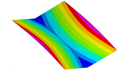
Delta T Offset For Bowing Effect in Assembly Process
In case of butt joint of two plates, in reality, there is an eccentricity e between the neutral phase of bending and the centre of the tendon force caused by the weld which causes the typical horse saddle of a butt welded flat plate.. A functionality Delta T Offset has been developed in order to overcome the limitation due to the shrinkage methodology that cannot provide correct results for a butt joint with a non-symmetrical welding. With this new development, it will be possible to apply an offset value on the thermal loading between upper and lower surfaces of shell. In consequence, the horse saddle effect of a butt welded flat plate is produced with Assembly solution.
Yonggang
Duan
Welding & Assembly
CFD-VIEW Colormap Options: Static, Dynamic, and Cumulative
The Colormap Settings panel in CFD-VIEW assigns colors to data sets. Identical data values on an object are displayed with the same color if they are using the same colormap display. Three options offer the user the opportunity to select the mode for updating the colormap as the underlying data changes, for example during transient simulations. These options are: Static, Dynamic, and Cumulative
Santosh
Kini
CFD
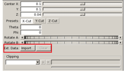
Importing an arbitrary STL surface for post-processing in CFD VIEW
When using the Arbitrary-Cut operator, you have the option to directly import an external surface in STL format into the model. This option, which was first made available in V2013.4, underwent significant performance improvements in V2014.0. This option provides the ability to plot data and process information on any arbitrarily shaped surface. The import process involves reading the STL file and computing the intersections between this surface and the model’s volume cells. Results on the imported surface are interpolated from the intersected volume cells and are independent of the surface mesh size of the STL as long as the surface is properly represented.
Abraham
Meganathan
CFD
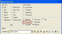
Grouping option for CFD-VIEW Data Import
Grouping feature in CFD-ACE+ GUI and CFD-VIEW comes in handy when working with complex industrial models. This feature allows putting BC patches or VC entities into a group that can be manipulated easily, to either set up properties or display specific post-processing attributes.
Abraham
Meganathan
CFD