Tips & Tricks
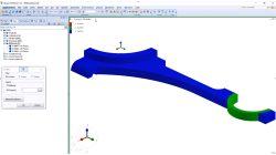
Material Properties visualization
Check material properties on model
Sandrine
Dischert
Multiphysics
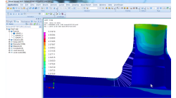
Cross Section Tool in Visual-SYSTUS
Cross-section creation becomes easy using the brand new Visual-SYSTUS cross-section tool !
Sandrine
Dischert
Multiphysics
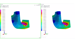
Coupling windows for postreatment visualization
When comparison between results is needed, coupling windows and synchronizing animations is a key tool.
Sandrine
Dischert
Multiphysics, Welding & Assembly, Virtual Integration Platform
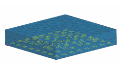
Boundary Layer Mesh tool demonstration
Easily creating a connection between a tetramesh and an hexamesh is possible, using Boundary Layer Mesh tool.
Sandrine
Dischert
Multiphysics, Welding & Assembly, Virtual Integration Platform

Using Region sources in CFD-VisCART
In order to control grid spacing at user-defined locations, mesh sources are a common tool in CFD-VisCART (Figure 1). Point, Line, Curve, Plane, Box and Surface sources have been available for several years. Cylinder and Sphere sources were introduced a few years back. To extend this tool set further, CFD-VisCART V2013.0 introduced Region sources.
Abraham
Meganathan
CFD

Automatic covering of larger unwanted holes in CFD-VisCART
CFD-VisCART meshing automatically closes or covers holes in the geometry that are smaller in size than the cell size specified at the surfaces. To cover LARGER holes, the ‘Max Hole Size to Cover’ feature can be used. This feature, introduced in V2013.2, works to automatically cover larger holes in the geometry during mesh generation, and thus prevents the mesh from leaking into unwanted regions. This feature is available with all mesh types supported in CFD-VisCART.
Abraham
Meganathan
CFD
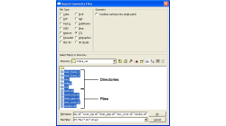
Grouping parts during data import in CFD-VisCART
When dealing with complex industrial models such as cars and airplanes, hundreds of parts need to be managed. Each one of these parts may also be subdivided into different components. In order to easily manipulate these different parts and components in CFD-VisCART, you can make use of the grouping feature.
Abraham
Meganathan
CFD

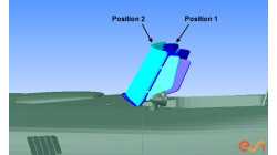
CFD-VisCART: Mesh Extrusion
In most CFD simulations, it is required to place inlets/outlets far enough from the region of interest in order to reduce their influence on the solution. In many applications, this can be done by extruding existing inlets/outlets BC patches away from the domain.
Abraham
Meganathan
CFD

Preserving boundaries between patches with CFD-VisCART’s Single Domain mesher
The ‘Preserve Features’ option does very well in preserving features between geometry patches – as long as the patches are not coplanar (dihedral angle = 0) or include a very small dihedral angle between them.
Abraham
Meganathan
CFD
CFD-VisCART: Suppression of parts for mesh generation
When performing an analysis comparing component A versus component B, it is useful to have both components stored in the same file for physical comparison and documentation purposes. However, when generating the mesh for the analysis, only one of the parts should be considered at a time. The "Suppress" option in CFD-VisCART makes this possible.
Abraham
Meganathan
CFD