Tips & Tricks
How to Obtain Best Results within Reasonable Time from a Heat Treatment Simulation
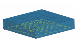
Heat treated parts are in most cases not clamped during heat treatment, for an FEM analysis, at least a static determined clamping is needed that does not allow any rigid body motion.
Yonggang
Duan
Welding & Assembly
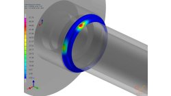
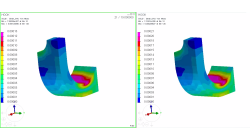
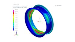
Stamping/HT Chaining of 3D Ring - Restart tool in Visual Heat Treatment
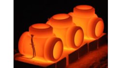
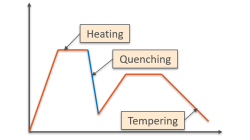
This article is to show effects of heat treatment on stresses when industrial mechanical parts are stamped (or welded) by 3 typical heat treatment steps: Heating, Quenching and Tempering. Tempering is generally considered effective in relieving stresses induced by quenching in addition to lowering hardness to within a specified range, or meeting certain mechanical property requirements.
Yonggang
Duan
Welding & Assembly
Heat Power display in Visual Weld
The aim of this development in Visual Weld 14.5 + Sysweld 2019.0 is to display the Power Density. Currently, this functionality is only available in the old SysWeld GUI. The new functionality "Heat Power Display" is available through the "Welding Utilities" menu of Visual Weld.
Yonggang
Duan
Welding & Assembly
Conversion Files .fdb in .erfh5 on Network Drive
It is not straightforward to do the conversion Files .fdb in .erfh5 on Network Drive in Visual Viewer. In order to make it work properly, it is necessary to map network drive to the local machine. In this way, the files on network could be handled like on local machine and the conversion from fdb to erf will be working properly.
Yonggang
Duan
Multiphysics, Welding & Assembly
Coupling windows for postreatment visualization
When comparison between results is needed, coupling windows and synchronizing animations is a key tool.
Sandrine
Dischert
Multiphysics, Welding & Assembly, Virtual Integration Platform
Boundary Layer Mesh tool demonstration
Easily creating a connection between a tetramesh and an hexamesh is possible, using Boundary Layer Mesh tool.
Sandrine
Dischert
Multiphysics, Welding & Assembly, Virtual Integration Platform
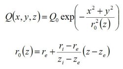
Heat Sources in Sysweld
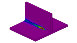
From finite element point of view, a heat source is modelled in SYSWELD by a volume density of energy named Qr (W/mm3) applied to elements, which move along the welding trajectory.
Yonggang
Duan
Welding & Assembly

Using Region sources in CFD-VisCART
In order to control grid spacing at user-defined locations, mesh sources are a common tool in CFD-VisCART (Figure 1). Point, Line, Curve, Plane, Box and Surface sources have been available for several years. Cylinder and Sphere sources were introduced a few years back. To extend this tool set further, CFD-VisCART V2013.0 introduced Region sources.
Abraham
Meganathan
CFD

Automatic covering of larger unwanted holes in CFD-VisCART
CFD-VisCART meshing automatically closes or covers holes in the geometry that are smaller in size than the cell size specified at the surfaces. To cover LARGER holes, the ‘Max Hole Size to Cover’ feature can be used. This feature, introduced in V2013.2, works to automatically cover larger holes in the geometry during mesh generation, and thus prevents the mesh from leaking into unwanted regions. This feature is available with all mesh types supported in CFD-VisCART.
Abraham
Meganathan
CFD
Weld Fatigue analysis based on the Dang Van Criteria
Numerical modeling of fatigue behavior has become critical for welding applications. For this purpose the ‘Dang Van criterion’ has been integrated in SYSWELD for fatigue evaluation of welded structure under multi-axial loadings. The Dang Van fatigue damage criterion is used to predict crack initiation and life duration of components subjected to damaging load. This criterion is based on multi-scale approach which assumes that shakedown occurs before crack initiation.
Harald
Porzner
Welding & Assembly