Tips & Tricks

Using Region sources in CFD-VisCART
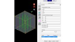
In order to control grid spacing at user-defined locations, mesh sources are a common tool in CFD-VisCART (Figure 1). Point, Line, Curve, Plane, Box and Surface sources have been available for several years. Cylinder and Sphere sources were introduced a few years back. To extend this tool set further, CFD-VisCART V2013.0 introduced Region sources.
Abraham
Meganathan
CFD
New Mesh Sources in CFD-GEOM for Triangle and Tetrahedral meshing
Corner Point Sources, Surface Interior Sources and Tet Sources have been available in CFD-GEOM for several years, allowing for refinements during certain phases of mesh generation.
Abraham
Meganathan
CFD
Importing an arbitrary STL surface for post-processing in CFD VIEW
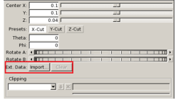
When using the Arbitrary-Cut operator, you have the option to directly import an external surface in STL format into the model. This option, which was first made available in V2013.4, underwent significant performance improvements in V2014.0. This option provides the ability to plot data and process information on any arbitrarily shaped surface. The import process involves reading the STL file and computing the intersections between this surface and the model’s volume cells. Results on the imported surface are interpolated from the intersected volume cells and are independent of the surface mesh size of the STL as long as the surface is properly represented.
Abraham
Meganathan
CFD
Using a template CDL file for quick case set up in CFD-CADalyzer
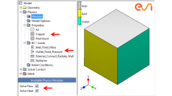
If your simulations with CFD-CADalyzer typically include the same or similar type of physics, materials and boundary conditions then you can make the case setup process very efficient and quick with the use of a template file - a CDL file that includes the typical simulation settings.
Abraham
Meganathan
CFD

Automatic covering of larger unwanted holes in CFD-VisCART
CFD-VisCART meshing automatically closes or covers holes in the geometry that are smaller in size than the cell size specified at the surfaces. To cover LARGER holes, the ‘Max Hole Size to Cover’ feature can be used. This feature, introduced in V2013.2, works to automatically cover larger holes in the geometry during mesh generation, and thus prevents the mesh from leaking into unwanted regions. This feature is available with all mesh types supported in CFD-VisCART.
Abraham
Meganathan
CFD
Model clipping feature in CFD-VisCART and CFD-GEOM
For better visualization of the geometry and mesh, a model clipping feature was introduced in CFD-VisCART and CFD-GEOM V2013.0. The following sections illustrate the usage and benefits of this feature.
Abraham
Meganathan
CFD
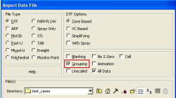
Grouping option for CFD-VIEW Data Import
Grouping feature in CFD-ACE+ GUI and CFD-VIEW comes in handy when working with complex industrial models. This feature allows putting BC patches or VC entities into a group that can be manipulated easily, to either set up properties or display specific post-processing attributes.
Abraham
Meganathan
CFD
Improve Productivity Using Scripts [Video Format]
As simulations become more integrated with the design process, engineers often spend time on repeated operations that do not contribute to their productivity. There is a need for tools that could capture, preserve and transfer the knowledge within the organization or to its customers.
Abraham
Meganathan
CFD

CFD-VIEW Scripting is easier than ever with Journaling
In addition to the numerous options and tools available via the CFD-VIEW user interface, the scripting capability of CFD-VIEW allows you to perform complex data processing on your simulation results, and gives you the option to run the post-processing phase of your simulation in batch mode.
Abraham
Meganathan
CFD
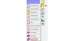
Working with Solids in CFD-GEOM - Part 1: Boolean Operations
Given that today’s users may import several complex parts into CFD-GEOM, this tip will demonstrate how to use the Solid Boolean Union Option to combine several parts into one.
Abraham
Meganathan
CFD