Tips & Tricks
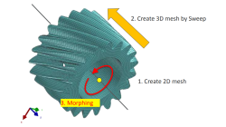
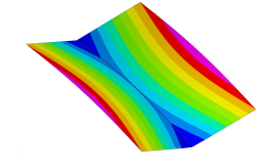
Solid elements morphing by twist in Visual Mesh
In the case of 3D meshes, the term morph can be interpreted as the change of appearance of a graphical object. The morphing process is then defined as the construction of an animated sequence corresponding to the gradual transition between two different objects, so-called source (initial) and target (final) models. The objective of a morphing method is to compute a transformation ensuring a visually pleasant transition between the two, source and target shapes
Mandikizinoyou
Taro
Multiphysics, Welding & Assembly
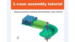
Demonstrator of typical Stamp-Assembly process in automotive BiW manufacturing
New Stamp-Assembly non-confidential tutorial available
Jan
Bejvl
Sheet Metal Forming, Welding & Assembly, Virtual Integration Platform
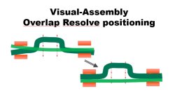
Visual-Assembly Overlap Resolve positioning
The most effective way how to position your distorted components into the clamping system.
Jan
Bejvl
Welding & Assembly, Virtual Integration Platform
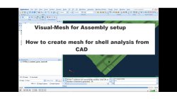
Visual-Mesh for Assembly setup - How to create mesh for shell analysis from CAD.
Short video how to create shell mesh from CAD using Visual-Mesh application.
Ksenia
Troyanova
Welding & Assembly, Virtual Integration Platform
Delta T Offset For Bowing Effect in Assembly Process
In case of butt joint of two plates, in reality, there is an eccentricity e between the neutral phase of bending and the centre of the tendon force caused by the weld which causes the typical horse saddle of a butt welded flat plate.. A functionality Delta T Offset has been developed in order to overcome the limitation due to the shrinkage methodology that cannot provide correct results for a butt joint with a non-symmetrical welding. With this new development, it will be possible to apply an offset value on the thermal loading between upper and lower surfaces of shell. In consequence, the horse saddle effect of a butt welded flat plate is produced with Assembly solution.
Yonggang
Duan
Welding & Assembly
Model clipping feature in CFD-VisCART and CFD-GEOM
For better visualization of the geometry and mesh, a model clipping feature was introduced in CFD-VisCART and CFD-GEOM V2013.0. The following sections illustrate the usage and benefits of this feature.
Abraham
Meganathan
CFD
Improve Productivity Using Scripts [Video Format]
As simulations become more integrated with the design process, engineers often spend time on repeated operations that do not contribute to their productivity. There is a need for tools that could capture, preserve and transfer the knowledge within the organization or to its customers.
Abraham
Meganathan
CFD

Boundary layer meshing with CFD-ACE+ [video format]
The accuracy of a CFD solution is strongly dependent on how well the mesh resolves geometry and flow features. This is especially true for near wall regions (boundary layer) where viscous forces are not negligible compared to inertial forces.
Abraham
Meganathan
CFD
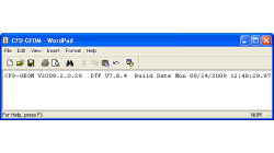
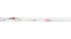
How to check what software version you are running
There is a very fast and easy way to verify what software version you are running for your ESI CFD applications. You most likely know that this information is available for the GUI by clicking on 'Help → About ...', and for solvers by looking in the output file.
Abraham
Meganathan
CFD
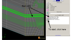
Always Make Sure You Have a Good Mesh Quality
The mesh has a great influence on the solver convergence and solution of every CFD Simulation. The user is strongly advised to check the quality of a numerical mesh.
Abraham
Meganathan
CFD