Tips & Tricks
CFD-VIEW: Save Smaller mdl Files
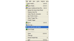
While working with CFD-VIEW, the user has the option of saving an mdl file. This file stores all the entities created in CFD-VIEW, from the point the DTF file (or other data file) was imported, to their current state at the time of saving. The user can thus reopen this file anytime later to resume work.
Abraham
Meganathan
CFD
Exporting STL Files From CFD-GEOM
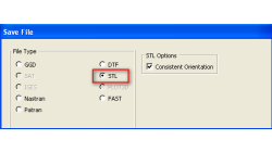
A CFD simulation process starts from an accurate representation of the boundaries that usually originates directly from CAD systems. STL and IGES are two of the most common output formats used as a starting point for mesh generation. STL (StereoLithography) files represent 3D surface geometries using a triangular mesh allowing unambiguous transfer of files from one system to another.
Abraham
Meganathan
CFD
Plotter Operations with CFD-VIEW
The Plotter operator in CFD-VIEW supports signal processing for Time History data. A previous user tip – Digital Signal Processing using CFD-VIEW – shows how time history date can be made available and how to perform a PSD on a periodic signal. The aim of this new user tip is to list all options supported by the Plotter Operator.
Abraham
Meganathan
CFD
Getting Average Quantities in CFD-VIEW
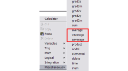
Many times, post-processing results requires computing average quantities of variables over a surface or volume. CFD-VIEW makes it easy with three calculator functions under the ‘Miscellaneous’ function category, as shown in Figure 1.
Abraham
Meganathan
CFD
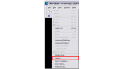
Using Levels in CFD-GEOM
Handling large models in CFD-GEOM is quite easy, but often there are thousands of entities, making it hard to sort out particular entities among them all. For cases like these, a visual grouping mechanism in CFD-GEOM makes viewing such models very efficient. Levels in CFD-GEOM are used as a visual grouping tool, allowing you to Show/Hide certain parts of your model easily and quickly
Abraham
Meganathan
CFD
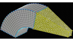
Hybrid Meshing in CFD-GEOM
Hybrid meshes can help in optimizing grids in complex geometries allowing for structured meshes in one part of a geometry, while using unstructured grids in more complex regions. This tip will show you how to create a simple hybrid (structured/tetrahedral) mesh system in CFD-GEOM, as shown in Figure 1.
Abraham
Meganathan
CFD
Creating Multiple Blocks from a Single Mouse Click
Computational Fluid Dynamics initiated in structured grid context for smooth and orthogonal structured grid on relatively simple geometries. Today, CFD has evolved encompass multi block and overlapping structured grid techniques for complex geometries, along with other mesh types such as tetrahedrals, polyhedrals, and prisms.
Abraham
Meganathan
CFD
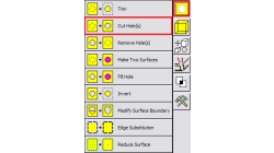
Handling Multiple holes for surface operations in CFD-GEOM
In the past, cutting or filling holes in surfaces with CFD-GEOM required a two step process; 1) pick the surface 2) pick the closed set of curves that forms the hole. Not a bad process but in the case of having to cut the surface with multiple holes, it was quite inefficient since you could only cut one hole at a time.
Abraham
Meganathan
CFD
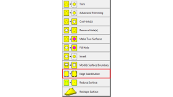
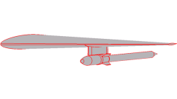
Edge Substitution for surfaces in CFD-GEOM
The Edge Substitution tool in CFD-GEOM is designed to make it easy to modify surface boundaries. It allows you to replace the lines/curve of a surface with edges, and vice versa.
Abraham
Meganathan
CFD
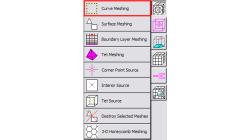
Local Curve Meshing in CFD-GEOM
Computational geometries/assemblies often involve parts that may vary in scale. Although unstructured surface meshing adapts to the size of the geometry, in some cases there may not be sufficient grid density in specific regions of your model.
Abraham
Meganathan
CFD