Tips & Tricks
How to model Cable Networks & Connectors?
This paper is aimed at describing the modeling process to be applied to the terminal connectors of a Cable Network when focusing on 3D/Multiconductor Transmission Lines (MTL) coupling
Jean-Claude
Kedzia
Electromagnetics
How to avoid oscillatory phenomena with short circuited terminals of Cable Networks ?
Cable Networks with short-circuited terminals may exhibit Common-Mode (CM) currents with a highly oscillatory behavior. This article illustrates one solution to eliminate such behavior by considering lossy dielectric coatings varying with the frequency.
Jean-Claude
Kedzia
Electromagnetics
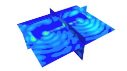
FD Interpolating Scheme near Metallic Structures
This article illustrates the PAM-CEM/FD interpolation scheme applied to compute the tangential electric field along wires’ path running near metallic structures (and aimed at avoiding the management of field components on both sides of the surface).
Jean-Claude
Kedzia
Electromagnetics
3D/Multiconductor Transmission Lines (MTL) Coupling VS. Stand-Alone FDTD (Accuracy)
This article is aimed at comparing the 3D/Multiconductor Transmission Lines (MTL) coupling accuracy with the PAM-CEM/FD stand-alone use, when applied to simplified wired models. Recommendations for good agreement are also proposed.
Jean-Claude
Kedzia
Electromagnetics
Internal injection lines modeling
Internal injection lines on a shell model (i.e. made of internal element edges) are not supported by the parallel solver.
Mathilde
Chabin
Composites

Direct Opening of a mesh
The creation of a RTM project and loading of the model mesh is usually done in 2 steps.
Mathilde
Chabin
Composites
Coupling between PAM-FORM and PAM-RTM: multiple part mapping
Coupling between PAM-FORM 2G and PAM-RTM is done through a .DSY file. Thus, pre-forming process is simulated with PAM-FORM 2G and resulting fiber orientations that will affect permeabilities are transferred to PAM-RTM model setup.
Mathilde
Chabin
Composites