Tips & Tricks

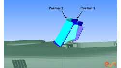
Part to part positioning based on mesh geometry
Sometimes the car coordinate system is not available with the stamped part. So if one wants to map stamp results, to an assembly operation, first of all the part needs to be transformed to the right position.
Matthias
Schroeder
Sheet Metal Forming

How to complete partial part on binder die design with “flat” part boundary?
In the following picture, the die entry radius in the addendum region should disappear smoothly in a flat surface (or infinite radius). In current version, there is no function to directly fulfill this need.
Marie
de Marguerye
Sheet Metal Forming

Preserving boundaries between patches with CFD-VisCART’s Single Domain mesher
The ‘Preserve Features’ option does very well in preserving features between geometry patches – as long as the patches are not coplanar (dihedral angle = 0) or include a very small dihedral angle between them.
Abraham
Meganathan
CFD
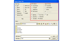
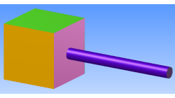
CFD-VisCART: Suppression of parts for mesh generation
When performing an analysis comparing component A versus component B, it is useful to have both components stored in the same file for physical comparison and documentation purposes. However, when generating the mesh for the analysis, only one of the parts should be considered at a time. The "Suppress" option in CFD-VisCART makes this possible.
Abraham
Meganathan
CFD
CFD-VIEW: Working with cell-center data in batch mode
Many improvements have been made in CFD-VIEW that allows the manipulation of cell-center data. The latest cell-center data additions implemented in CFD-VIEW V2011.0 include, for example, support for the MinMax Probe and the Calculator.
Abraham
Meganathan
CFD
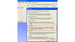
"Per Pixel Lighting" display option in CFD-VIEW
When visualizing CFD solutions, it is often of interest to see a particular range of variable values, and it is therefore useful to be able to clip the surface coloring to that range, as to obtain a clearer view of the areas affected by the variable.
Abraham
Meganathan
CFD
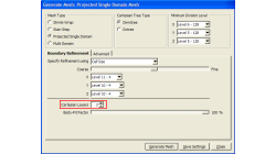
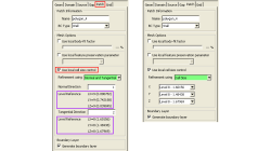
Boundary Layer meshing in CFD-VisCART
In order to accurately capture flow field characteristics, a fine mesh near boundary walls is often needed. This is commonly referred to as the Boundary Layer mesh or simply, Boundary Layers. When dealing with structured meshes, one would cluster grid points near specific boundaries before building mesh faces and blocks. But for an automated mesher, dedicated algorithms are needed to generate boundary layer cells. Both CFD-GEOM and CFD-VisCART are capable of generating boundary layer meshes, and they share the same core algorithm.
Abraham
Meganathan
CFD
"Preserve Feature" option in CFD-VisCART
When dealing with the multi-domain mesher in CFD-VisCART, the ‘Preserve Feature’ option can help you get a mesh that closely follow the original geometry. The meshing algorithm controls the refinement based on the detected ‘Critical Features’ or ‘Outlines’. Therefore, it is very important to detect critical features and outlines prior to mesh generation.
Abraham
Meganathan
CFD
Local cell size control option in CFD-VisCART
It is often necessary to refine or coarsen the mesh in some regions of your model, whether it be to allow the solver to correctly capture gradients of variables (refinement), or reduce the mesh density in some areas to lower the total cell count. In CFD-VisCART, there are many options that enable local mesh refinement.
Abraham
Meganathan
CFD
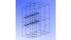
Visualizing decomposed model without zonal interface outlines
Running a simulation in parallel allows quicker turn around for larger and complex problems. Such parallel jobs require the computational domain to be decomposed into multiple zones. Such a multiple-zone file may be inconvenient to post-process in CFD-VIEW because zonal interface outlines will be visible and the original surfaces would have been split. As depicted in figure 1 below, these outlines can be numerous and may therefore hinder the clarity of the model.
Abraham
Meganathan
CFD