Tips & Tricks
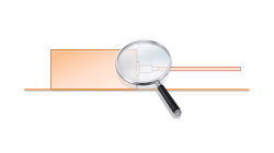
How to model Cable Networks & Connectors?
This paper is aimed at describing the modeling process to be applied to the terminal connectors of a Cable Network when focusing on 3D/Multiconductor Transmission Lines (MTL) coupling
Jean-Claude
Kedzia
Electromagnetics
How to avoid oscillatory phenomena with short circuited terminals of Cable Networks ?
Cable Networks with short-circuited terminals may exhibit Common-Mode (CM) currents with a highly oscillatory behavior. This article illustrates one solution to eliminate such behavior by considering lossy dielectric coatings varying with the frequency.
Jean-Claude
Kedzia
Electromagnetics
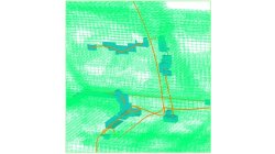
FD Interpolating Scheme near Metallic Structures
This article illustrates the PAM-CEM/FD interpolation scheme applied to compute the tangential electric field along wires’ path running near metallic structures (and aimed at avoiding the management of field components on both sides of the surface).
Jean-Claude
Kedzia
Electromagnetics
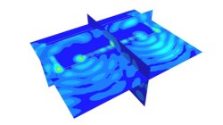
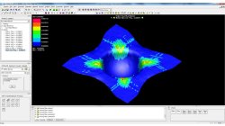
3D/Multiconductor Transmission Lines (MTL) Coupling VS. Stand-Alone FDTD (Accuracy)
This article is aimed at comparing the 3D/Multiconductor Transmission Lines (MTL) coupling accuracy with the PAM-CEM/FD stand-alone use, when applied to simplified wired models. Recommendations for good agreement are also proposed.
Jean-Claude
Kedzia
Electromagnetics
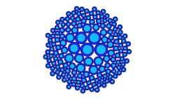
Fiber volume content contour
Two dedicated composites contours are available in PAM-FORM 2G post-processing: Shear angle and fiber directions.
Mathilde
Chabin
Composites
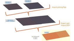
Coupling between PAM-FORM and PAM-RTM: multiple part mapping
Coupling between PAM-FORM 2G and PAM-RTM is done through a .DSY file. Thus, pre-forming process is simulated with PAM-FORM 2G and resulting fiber orientations that will affect permeabilities are transferred to PAM-RTM model setup.
Mathilde
Chabin
Composites
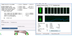
How to report and talk about simulation time in an objective manner
Reporting or talking about simulation time is a difficult subject. In the article a way to manage this problem in an objective manner is given.
Harald
Porzner
Welding & Assembly

Materials in the database - Which material properties to use with respect to the three methods to simulate the heat effects of welding
A material is described with exactly one set of material properties. In simulation engineering - depending on the applied method and the moment in time when the simulation is carried out in the product development cycle - only subsets of a full material data set might be required. In this article is outlined which subset is used for which purpose, what is available in the database, and what can be simulated.
Harald
Porzner
Welding & Assembly
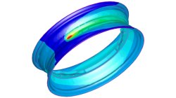
The transient method – the third out of three methods to simulate the heat effects of welding
In order to meet different requirements from first design to start of production, three different methods are available in the Virtual Welding & Assembly Suite from ESI. The third one – the transient method – is used when not only distortion but also residual stresses and microstructure need to be evaluated. The part size allows running a heat source gradually. Compare it with a formability evaluation in sheet metal forming. A motorcycle rim may serve as an example.
Harald
Porzner
Welding & Assembly
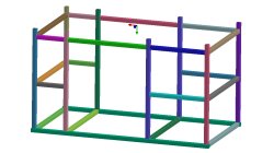
The instantaneous method – the second out of three methods to simulate the heat effects of welding
In order to meet different requirements from first design to start of production, three different methods are available in the Virtual Welding & Assembly Suite from ESI. The second one – the instantaneous method – is used when not only distortion but also residual stresses and micro-structure needs to be evaluated, but welded designs are so huge that it would make no more sense to use a classic transient method with a moving heat source – the simulation time would be too long. Compare it with a feasibility evaluation in sheet metal forming. A frame as produced in machine building, with more than 100 welds, may serve as an example.
Harald
Porzner
Welding & Assembly