Tips & Tricks
How to report and talk about simulation time in an objective manner
Reporting or talking about simulation time is a difficult subject. In the article a way to manage this problem in an objective manner is given.
Harald
Porzner
Welding & Assembly

Materials in the database - Which material properties to use with respect to the three methods to simulate the heat effects of welding
A material is described with exactly one set of material properties. In simulation engineering - depending on the applied method and the moment in time when the simulation is carried out in the product development cycle - only subsets of a full material data set might be required. In this article is outlined which subset is used for which purpose, what is available in the database, and what can be simulated.
Harald
Porzner
Welding & Assembly
The transient method – the third out of three methods to simulate the heat effects of welding
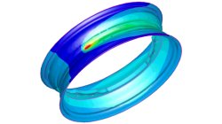
In order to meet different requirements from first design to start of production, three different methods are available in the Virtual Welding & Assembly Suite from ESI. The third one – the transient method – is used when not only distortion but also residual stresses and microstructure need to be evaluated. The part size allows running a heat source gradually. Compare it with a formability evaluation in sheet metal forming. A motorcycle rim may serve as an example.
Harald
Porzner
Welding & Assembly
The instantaneous method – the second out of three methods to simulate the heat effects of welding
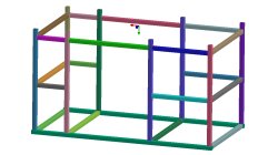
In order to meet different requirements from first design to start of production, three different methods are available in the Virtual Welding & Assembly Suite from ESI. The second one – the instantaneous method – is used when not only distortion but also residual stresses and micro-structure needs to be evaluated, but welded designs are so huge that it would make no more sense to use a classic transient method with a moving heat source – the simulation time would be too long. Compare it with a feasibility evaluation in sheet metal forming. A frame as produced in machine building, with more than 100 welds, may serve as an example.
Harald
Porzner
Welding & Assembly
The shrinkage method – the first out of three methods to simulate the heat effects of welding
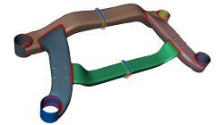
In order to meet different requirements from first design to start of production, three different methods are available in the Virtual Welding & Assembly Suite from ESI. The first one – the shrinkage method – is used in the feasibility and planning phase. Goal is to get as fast as possible an estimation. Compare it with a one-step method in sheet metal forming.
Harald
Porzner
Welding & Assembly
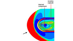
CFD-FASTRAN/CFD-ACE+ coupling for thermal environment simulations
In certain applications, different regions of the computational domain experiences flow conditions that are so different that it is very difficult for a single solver to produce accurate results at the extremes. In many situations, such problems can be separated and solved using loosely coupled solvers. Each solver is chosen to provide highly accurate solutions for the prevailing flow conditions.
Abraham
Meganathan
CFD
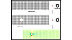
Avoiding Chimera Errors in CFD-FASTRAN
This note discusses a common error encountered by users when trying chimera meshes in CFD-FASTRAN. Such errors are easy to avoid and hopefully this note will assist you.
Abraham
Meganathan
CFD
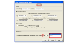
Motion Model Dependencies in CFD-FASTRAN
Moving-body models available in CFD-FASTRAN are highly suited to simulate complex prescribed and six-degree-of-freedom (6DOF) motions of rigid bodies. In many engineering problems, this translates to multiple bodies moving relative to one another.
Abraham
Meganathan
CFD
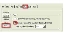
Low Mach Preconditioning and Dual Time Stepping in CFD-FASTRAN
Density-based schemes employing time-marching procedures available in CFD-FASTRAN provide excellent stability and convergence characteristics for high-speed compressible flows (typically M >0.5).
Abraham
Meganathan
CFD
Axisymmetric 2D Convergent-Divergent Boattail Nozzle Simulation Using CFD-FASTRAN
The NASA D-1.22-L boattail nozzle configuration was obtained from the MADIC (Multidisciplinary and Design Industrial Consortium) program. The geometry definition and the flow conditions are documented in NASA TP 1766 [1]. This user tip presents a validation of numerical methods against experimental data.
Abraham
Meganathan
CFD