Tips & Tricks

Using Region sources in CFD-VisCART
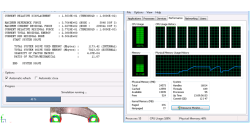
In order to control grid spacing at user-defined locations, mesh sources are a common tool in CFD-VisCART (Figure 1). Point, Line, Curve, Plane, Box and Surface sources have been available for several years. Cylinder and Sphere sources were introduced a few years back. To extend this tool set further, CFD-VisCART V2013.0 introduced Region sources.
Abraham
Meganathan
CFD

Automatic covering of larger unwanted holes in CFD-VisCART
CFD-VisCART meshing automatically closes or covers holes in the geometry that are smaller in size than the cell size specified at the surfaces. To cover LARGER holes, the ‘Max Hole Size to Cover’ feature can be used. This feature, introduced in V2013.2, works to automatically cover larger holes in the geometry during mesh generation, and thus prevents the mesh from leaking into unwanted regions. This feature is available with all mesh types supported in CFD-VisCART.
Abraham
Meganathan
CFD
How to report and talk about simulation time in an objective manner
Reporting or talking about simulation time is a difficult subject. In the article a way to manage this problem in an objective manner is given.
Harald
Porzner
Welding & Assembly

Materials in the database - Which material properties to use with respect to the three methods to simulate the heat effects of welding
A material is described with exactly one set of material properties. In simulation engineering - depending on the applied method and the moment in time when the simulation is carried out in the product development cycle - only subsets of a full material data set might be required. In this article is outlined which subset is used for which purpose, what is available in the database, and what can be simulated.
Harald
Porzner
Welding & Assembly
The transient method – the third out of three methods to simulate the heat effects of welding
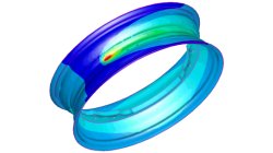
In order to meet different requirements from first design to start of production, three different methods are available in the Virtual Welding & Assembly Suite from ESI. The third one – the transient method – is used when not only distortion but also residual stresses and microstructure need to be evaluated. The part size allows running a heat source gradually. Compare it with a formability evaluation in sheet metal forming. A motorcycle rim may serve as an example.
Harald
Porzner
Welding & Assembly
The instantaneous method – the second out of three methods to simulate the heat effects of welding
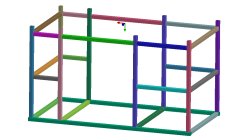
In order to meet different requirements from first design to start of production, three different methods are available in the Virtual Welding & Assembly Suite from ESI. The second one – the instantaneous method – is used when not only distortion but also residual stresses and micro-structure needs to be evaluated, but welded designs are so huge that it would make no more sense to use a classic transient method with a moving heat source – the simulation time would be too long. Compare it with a feasibility evaluation in sheet metal forming. A frame as produced in machine building, with more than 100 welds, may serve as an example.
Harald
Porzner
Welding & Assembly
The shrinkage method – the first out of three methods to simulate the heat effects of welding
In order to meet different requirements from first design to start of production, three different methods are available in the Virtual Welding & Assembly Suite from ESI. The first one – the shrinkage method – is used in the feasibility and planning phase. Goal is to get as fast as possible an estimation. Compare it with a one-step method in sheet metal forming.
Harald
Porzner
Welding & Assembly
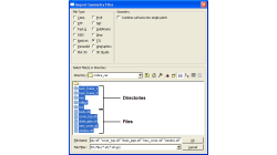
Grouping parts during data import in CFD-VisCART
When dealing with complex industrial models such as cars and airplanes, hundreds of parts need to be managed. Each one of these parts may also be subdivided into different components. In order to easily manipulate these different parts and components in CFD-VisCART, you can make use of the grouping feature.
Abraham
Meganathan
CFD

CFD-VisCART: Mesh Extrusion
In most CFD simulations, it is required to place inlets/outlets far enough from the region of interest in order to reduce their influence on the solution. In many applications, this can be done by extruding existing inlets/outlets BC patches away from the domain.
Abraham
Meganathan
CFD

Preserving boundaries between patches with CFD-VisCART’s Single Domain mesher
The ‘Preserve Features’ option does very well in preserving features between geometry patches – as long as the patches are not coplanar (dihedral angle = 0) or include a very small dihedral angle between them.
Abraham
Meganathan
CFD